The ESP8266 ESP12F Relay X16 Board
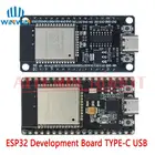
This 16 channel relay board is equipped with an ESP8266 12F. It can be programmed with an USB-TTL adapter with the Arduino IDE.
The Board
The microcontroller is an ESP8266 12F and can be programmed with the Arduino IDE. I use the settings of the NodeMCU 0.9 for the upload.
16 relays are connected to two 74HC595 shift registers. The outputs are HIGH active. The shift registers are connected to GPIO12, GPIO13, GPIO14 and GPIO5 (?).
Some GPIOs are available on separate headers, but remember, that GPIO2 is also connected to the (blue) LED on the ESP itself. The ADC is also available on the header. You can solder a header to gain access to following pins:
P1:
- 3V3
- TXd - GPIO1
- RXd - GPIO3
- GND
- GND
- IO0 - GPIO0 - connect to GND and reboot (power cycle) if you need to set the ESP8266 in flash mode
P2:
- 3V3
- GND
- ADC - A0 - the analog input of the ESP8266
- EN
- IO16 (Wake -> Reset)
- IO14 74HC595
- IO12 74HC595
- IO13 74HC595
P3
- 3V3
- GND
- IO5 (default I2C SCL)
- IO4 (default I2C SDA)
- IO0 - GPIO0 - connect to GND and reboot (power cycle) if you need to set the ESP8266 in flash mode
- IO2 - GPIO2 - also used for the (blue) LED on the ESP8266
- IO15
- GND
The 6 pins of the ESP8266 12F lower side are not connected to the PCB. If you need to use these IOs (11, 7, 9, 10, 8, 6), you have to solder them directly to the ESP but keep in mind that most of them are used by the ESP8266 core internally.
The board can be supplied with DC 5V or DC12 or DC24 depending on the version you bought.
How to program the Relay Board
The board can be programmed when you connect a USB-TTL to the respective header pins. RX/TX/GND and 3V3 are available on the header. To bring the ESP in flash mode connect IO0 to GND, press reset on the board and start the upload with the Arduino IDE. After the upload has finished, disconnect IO0 from GND and reset the board.
A simple Demo Sketch
I have put together a generic demo sketch. It is a simple ESP8266 webserver to switch the relays on or off. You can download this sketch at the end of this page.
The sketch offers several hardware variants / pin mappings and you must set the respective board in the main tab. The predefined pin mapping for this relay board is 72
#define USE_BOARD 72 // the ESP8266 16 channel board
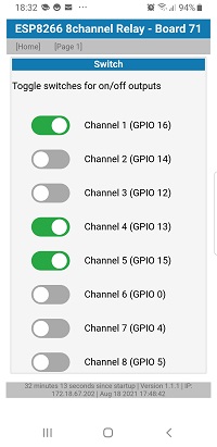
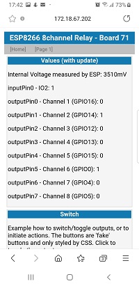
Page 1.htm is just for debugging. It shows the states of all pins and offers simple toggle buttons to switch the relays.
Exkurs: The Generic Demo Sketch
In general the generic sketch uses arrays of pin definitions. This makes maintenance for different boards very easy.
Before the first compile, go to the main tab and define which board variant you are using.
For this relay board use:
#define USE_BOARD 72
If you want to modify the configuration open tab config72.h
First you set a board name, this will be printed to serial and on the web GUI:
#if USE_BOARD == 72
#define TXT_BOARDNAME "ESP12F Relay X16" // the name of the board
All debug debug messages are printed to an interface called "Terminal". This board uses TX0, so just define a reference to Serial:
HardwareSerial &Terminal = Serial;
Then you declare all the pins:
const uint8_t flashPin = 0;   // GPIO00/D3 on NodeMCU the flash Button - this is for testing an input
const uint8_t inputAPin = 15; // GPIO15/D8 on NodeMCU
const uint8_t stcpPin = 12;   // GPIO12 74x595 RCLK/STCP
const uint8_t shcpPin = 13;   // GPIO13 74x595 SRCLK/SHCP
const uint8_t serPin = 14;    // GPIO14 74x595 SER/DS
const uint8_t oePin = 5;      // GPIO05 74x595 OE/output enable active low
Now you can assign these pins to the arrays. Start with the input pin, currently I'm using only pin 15 (as it is available on my testboard) and the flash pin because the button is on the board:
Pin inputPin[] {
// the pin a name for the website
  {inputAPin, "External"},
  {flashPin, "Flash Jumper"},
};
Then assign the 16 shift register pins to your outputs. The prompter will be printed in the web GUI and you must define if the relay is HIGH active (or LOW active). On this board all relays are HIGH active:
OutputPin shiftPin[] {
// the pin a name LOW active (or high active)
  {0, "Shift A", HIGH},
  {1, "Shift B", HIGH},
  {2, "Shift C", HIGH},
  {3, "Shift D", HIGH},
  {4, "Shift E", HIGH},
  {5, "Shift F", HIGH},
  {6, "Shift G", HIGH},
  {7, "Shift H", HIGH},
  {8, "Shift I", HIGH},
  {9, "Shift J", HIGH},
  {10, "Shift K", HIGH},
  {11, "Shift L", HIGH},
  {12, "Shift M", HIGH},
  {13, "Shift O", HIGH},
  {14, "Shift P", HIGH},
  {15, "Shift Q", HIGH},
};
This board doesn't have MOSFETs for PWM outputs, so instead of an array set following precompiler #define:
#define NO_PWMPIN
Finally, you can use the blue LED on the ESP8266 to indicate WiFi activity. If you need the LED for something different, set the variable to 255.
const byte wifiActivityPin = ledEspPin; // use ledEspPin or set to 255
#endif
This concludes the configuration of the ESP8266 16 channel relay board.
Don't forget to either set your WiFi credentials or include your settings in the main tab.
This generic webserver sketch is compatible for ESP8266 and the ESP32, hence the precompiler defines to differentiate the boards based on your upload settings. If you want to read more about the generic ESP webserver sketch - see this page: Simple ESP webserver.
Pricing of the ESP8266 ESP12F Relay X16 Relay Board
This 16 channel relay board is available for less than 30 EUR including shipping and VAT. It might not be a super cheap offer, but if you just need a relay board with an ESP8266, a DC/DC converter and don't want to wire three separate boards - take it!
Summary on the ESP8266 ESP12F Relay X16 Relay Board
This 16 channel relay board is a compact solution if you need as many as 16 relays driven by a single ESP8266.