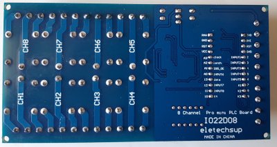
Das IO22D08 8 Channel Pro mini PLC Board
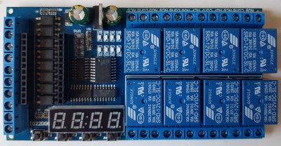
Schon lange ware ich auf der der Suche nach einer "Arduino Plug and Play" Variante für 8 Relais. Ich wollte einfach eine fertige Variante die ohne Dupont Kabel auskommt und "Arduino kompatibel" ist. Und seht mal was ich gefunden habe die IO22D08 - eine 8fach Relaiskarte für den Arduino Pro Mini mit einer LED Sieben Segment Anzeige.
Gut, es ist für einen Arduino Pro Mini, aber der lässt sich - mit einem USB-TTL Adapter - analog einem Uno mit der Arduino IDE programmieren. Daher habe ich mal eine Probebestellung gewagt und erste Tests durchgeführt.
Zum Aufbau
Die zusätzlichen Ausgänge werden mit Hilfe von drei 74HC595 Shiftregister gewonnen. Am Shiftregister U5 sind die Relais nicht aufsteigend angeschlossen sondern in der Reihenfolge 81234567. Der Enable Eingang des Shiftregisters für die Relais ist mit Pin A1 verbunden. Damit kann man die Ausgänge aktivieren nachdem die Initialisierung vorgenommen wurde oder eine Notabschaltung realisieren.
Für die 4 stellige 7 Segment Anzeige werden zwei weitere Shiftregister (U3 U4) verwendet. Die 7 Segment Anzeige zeigt gem Schaltplan nur 18:88 wird aber analog den Bildern mit einem 8.8.:8.8. geliefert. Das Display ist Common Cathode und direkt auf der Platine ungesockelt verlötet. Um die LED Anzeige im Multiplex ansteuern zu können, müssen permanent Daten an die Shiftregister gesandt werden. Ein LED Treiber wie ein HT16K33 oder MAX7219 wäre wohl besser gewesen. Als Datapin für die Shiftregister wurde Pin 13 gewählt, daher flackert/glimmt die Arduino Pro Mini LED.
Weiters sind 8 Eingänge mit Optokoppler versehen (zu beschalten gegen GND) und mit Schraubterminals nach außen geführt.
Weiters sind 4 Taster auf der Platine angebracht.
Die Pins A4/A5 können somit für I2C genutzt werden. Am Pro Mini sind (wie beim Nano) die Ports A6/A7 auch verfügbar. D. h. man hat neben TX/RX noch insgesamt 4 weitere GPIOs zur freien Verfügung. Dabei sind die Einschränkungen von A6/A7 zu beachten, aber das ist jetzt nicht das Thema.
Der Arduino Pro Mini wird im Sockel mittels VCC = 5V versorgt, es muss daher ein Pro Mini in der 5V Variante verwendet werden. Für einen Pro Mini 3.3 braucht es eine geringfügige Modifikation um die 5V auf RAW zu verlegen.
Der VIN Eingang ist lt Schaltplan mit einer Diode gegen Verpolung geschützt. Für die Spannungsregelung auf 5 V wird ein einfacher Linearregler verwendet (gem. Schaltplan soll es einen Widerstand R0 geben, mit dem der Spannungsregler überbrückt werden kann, den konnte ich auf der Platine aber noch nicht ausmachen). Im laufenen Betrieb mit aktivem Display wird der Regler nur geringfügig warm.
Die Platine hat keine Ausfräsungen / Vorbereitungen gegen Kriechstrecken, daher nicht am 230V Stromnetz betreiben!
Die Abmessungen der Platine betragen 120*62*19mm.
Software
Der Mustersketch ist für chinesische Verhältnisse fast schon gut dokumentiert. Auch die verwendete Timer-Library wird mitgeliefert. Dieser sorgt für das laufende Aktualisieren des Displays.
Das Beispiel macht eigentlich nur 8 "Nachlauf-Relais": tastet man einen der Optokoppler-Eingänge gegen GND, schaltet das zugeordnete Relais für eine bestimmte Zeit ein. Mit den Tasten 1 - 4 können die Zeitparamter der ersten vier Relais abgefragt werden, bzw. die Restzeit der Laufzeit angezeigt werden.
Ein adaptierter Sketch für das IO22D08
Mir hat die Verwendung des Timers nicht gefallen und überhaupt waren mir die Funktionen ein wenig zu verworren. Die drei Shift Register werden in einer Kette angesprochen. Da das Display wie oben beschrieben multiplext, muss mann auch jedesmal die Relais in die Register shiften. Daher habe ich eine Basisklasse IO22D08 erstellt, die die Hardware der Shiftregister (Relais und Display) implementiert. Die Basisklasse stellt die Hardwarezugriffe für das Board zur Verfügung und kann in allen Sketchen unverändert wiederverwendet werden.
Von der Basisklasse wird für den eigentlichen Sketch die Klasse IO22D08timer abgeleitet. Diese Klasse erbt alle Methoden der Basisklasse und enthält zusätzlich weitere Variablen und Methoden für die Zeitsteuerung. Die Vererbung hat mir für diesen Zweck besser gefallen als zwei getrennte Klassen. Das Objekt board ist somit die Instanz von IO22D08timer die alle Methoden beherrscht:
Die Optokoppler und Taster werden in einer simplen Funktion gelesen. Alles zusammen finde ich der Sketch ist nun besser lesbar und leichter für seine Zwecke adaptierbar.
/* IO22D08 DC 12V 8 Channel Pro mini PLC Board Relay Shield Module for Arduino Multifunction Delay Timer Switch Board Hardware: 4 bit Common Cathode Digital Tube Module (two shift registers) 8 relays (one shift register) 8 optocoupler 4 discrete input keys (to GND) ---Segment Display Screen---- --A-- F---B --G-- E---C --D-- __ __ __ __ |__||__|.|__||__| |__||__|'|__||__| ---------------------- available on Aliexpress: https://s.click.aliexpress.com/e/_A0tJEK some code parts based on the work of cantone-electonics http://www.canton-electronics.com this version by noiasca 2021-04-01 OOP (2340/122) 2021-03-31 initial version (2368/126) 1999-99-99 OEM Version (2820/101) */ //Pin connected to latch of Digital Tube Module // ST Store // de: Der Wechsel von Low auf High kopiert den Inhalt des Shift Registers in das Ausgaberegister bzw. Speicherregister const uint8_t latchPin = A2; //Pin connected to clock of Digital Tube Module // SH clock Shift Clock Pin //de: Übernahme des Data Signals in das eigentliche Schieberegister const uint8_t clockPin = A3; //Pin connected to data of Digital Tube Module const uint8_t dataPin = 13; //Pin connected to 595_OE of Digital Tube Module // Output Enable to activate outputs Q0 – Q7 - first device: Relay IC const uint8_t OE_595 = A1; // A4 - unused - not connected - I2C SDA // A5 - unused - not connected - I2C SCL // A6 - unused - not connected // A7 - unused - not connected const uint8_t optoInPin[] {2, 3, 4, 5, 6, A0, 12, 11}; // the input GPIO's with optocoupler - LOW active const uint8_t keyInPin[] {7, 8, 9, 10}; // the input GPIO's with momentary buttons - LOW active const uint8_t noOfOptoIn = sizeof(optoInPin); // calculate the number of opto inputs const uint8_t noOfKeyIn = sizeof(keyInPin); // calculate the number of discrete input keys const uint8_t noOfRelay = 8; // relays on board driven connected to shift registers byte key_value; // the last pressed key // the base class implements the basic functionality // which should be the same for all sketches with this hardware: // begin() init the hardware // setNumber() send an integer to the internal display buffer // pinWrite() switch on/off a relay // update() refresh the display // tick() keep internals running class IO22D08 { protected: uint8_t dat_buf[4]; // the display buffer - reduced to 4 as we only have 4 digits on this board uint8_t relay_port; // we need to keep track of the 8 relays in this variable uint8_t com_num; // Digital Tube Common - actual digit to be shown uint32_t previousMillis = 0; // time keeping for periodic calls // low level HW access to shift registers // including mapping of pins void update() { static const uint8_t TUBE_NUM[4] = {0xfe, 0xfd, 0xfb, 0xf7}; // Tuble bit number - the mapping to commons // currently only the first 10 characters (=numbers) are used, but I keep the definitions // NO.:0,1,2,3,4,5,6,7,8,9,10,11,12,13,14,15,16,17,18,19,20,21,22 23 24 25 26 27 28*/ // Character :0,1,2,3,4,5,6,7,8,9,A, b, C, c, d, E, F, H, h, L, n, N, o, P, r, t, U, -, ,*/ const uint8_t TUBE_SEG[29] = {0xc0, 0xf9, 0xa4, 0xb0, 0x99, 0x92, 0x82, 0xf8, 0x80, 0x90, 0x88, 0x83, 0xc6, 0xa7, 0xa1, 0x86, 0x8e, 0x89, 0x8b, 0xc7, 0xab, 0xc8, 0xa3, 0x8c, 0xaf, 0x87, 0xc1, 0xbf, 0xff}; uint8_t tube_dat; // Common Cathode Digital Tube, bit negated - sum of all segments to be activated uint8_t bit_num; // digital tube common gemappt auf tuble bit number uint8_t display_l, display_h, relay_dat; // three databytes of payload to be shifted to the shift registers if (com_num < 3) com_num ++; else com_num = 0; // next digit uint8_t dat = dat_buf[com_num]; // Data to be displayed tube_dat = TUBE_SEG[dat]; // Common Cathode Digital Tube, bit negated - sum of all segments bit_num = ~TUBE_NUM[com_num]; // digital tube common gemappt auf tuble bit number display_l = ((tube_dat & 0x10) >> 3); //Q4 <-D1 -3 SEG_E display_l |= ((bit_num & 0x01) << 2); //DIGI0<-D2 +2 display_l |= ((tube_dat & 0x08) >> 0); //Q3 <-D3 0 SEG_D display_l |= ((tube_dat & 0x01) << 4); //Q0 <-D4 -4 SEG_A display_l |= ((tube_dat & 0x80) >> 2); //Q7 <-D5 -2 SEG_DP - Colon - only on digit 1 ? display_l |= ((tube_dat & 0x20) << 1); //Q5 <-D6 1 SEG_F display_l |= ((tube_dat & 0x04) << 5); //Q2 <-D7 5 SEG_C // output U3-D0 is not connected, // on the schematic the outputs of the shiftregisters are internally marked with Q, here we use U3-D to refeer to the latched output) display_h = ((bit_num & 0x02) >> 0); //DIGI1<-D1 0 display_h |= ((bit_num & 0x04) >> 0); //DIGI2<-D2 0 display_h |= ((tube_dat & 0x40) >> 3); //Q6 <-D3 -3 SEG_G display_h |= ((tube_dat & 0x02) << 3); //Q1 <-D4 3 SEG_B display_h |= ((bit_num & 0x08) << 2); //DIGI3<-D5 2 // Outputs U4-D0, U4-D6 and U4-D7 are not connected relay_dat = ((relay_port & 0x7f) << 1); // map Pinout 74HC595 to ULN2803: 81234567 relay_dat = relay_dat | ((relay_port & 0x80) >> 7); //ground latchPin and hold low for as long as you are transmitting digitalWrite(latchPin, LOW); // as the shift registers are daisy chained we need to shift out to all three 74HC595 // hence, one single class for the display AND the relays ... // de: das ist natürlich ein Käse dass wir hier einen gemischten Zugriff auf das Display und die Relais machen müssen shiftOut(dataPin, clockPin, MSBFIRST, display_h); // data for U3 - display shiftOut(dataPin, clockPin, MSBFIRST, display_l); // data for U4 - display shiftOut(dataPin, clockPin, MSBFIRST, relay_dat); // data for U5 - Relay //return the latch pin high to signal chip that it no longer needs to listen for information digitalWrite(latchPin, HIGH); } public: IO22D08() {} void begin() { digitalWrite(OE_595, LOW); // Enable Pin of first 74HC595 pinMode(latchPin, OUTPUT); pinMode(clockPin, OUTPUT); pinMode(dataPin, OUTPUT); pinMode(OE_595, OUTPUT); } // fills the internal buffer for the digital outputs (relays) void pinWrite(uint8_t pin, uint8_t mode) { // pin am ersten shiftregister ein oder ausschalten if (mode == LOW) bitClear(relay_port, pin); else bitSet(relay_port, pin); update(); // optional: call the shiftout process (but will be done some milliseconds later anyway) } // this is a first simple "print number" method // right alligned, unused digits with zeros // should be reworked for a nicer print/write void setNumber(int display_dat) { dat_buf[0] = display_dat / 1000; display_dat = display_dat % 1000; dat_buf[1] = display_dat / 100; display_dat = display_dat % 100; dat_buf[2] = display_dat / 10; dat_buf[3] = display_dat % 10; } // this method should be called in loop as often as possible // it will refresh the multiplex display void tick() { uint32_t currentMillis = millis(); if (currentMillis - previousMillis > 1) // each two milliseconds gives a stable display on pro Mini 8MHz { update(); previousMillis = currentMillis; } } }; // the timer class extends the basic IO22D08 board // with some timers for the relays // this is the specific implementation for this sketch class IO22D08timer : public IO22D08 { protected: bool isActive[noOfRelay]; // timer of this relay is running uint32_t previousTimer[noOfRelay]; // start time of relay public: IO22D08timer() : IO22D08() {} uint16_t delay_time[noOfRelay]; // delay time of this relay - I'm to lazy to write a setter, therefore public void startTimer(byte actual) { // start the timer and activate the output previousTimer[actual] = millis(); isActive[actual] = true; pinWrite(actual, HIGH); } void tickTimer() { // a specialised "tick" method avoiding a virtual/override, hence the different name uint32_t currentMillis = millis(); if (currentMillis - previousMillis > 1) // each two milliseconds gives a stable display on pro Mini 8MHz (3ms will flicker) { // 01 check if there is something to do for the relay timers: for (size_t i = 0; i < noOfRelay; i++) { if (isActive[i]) // check for switch off { if (currentMillis - previousTimer[i] > delay_time[i] * 1000UL) { isActive[i] = false; pinWrite(i, LOW); } } } // 02 update the output buffer if (isActive[key_value]) setNumber(delay_time[key_value] - (millis() - previousTimer[key_value]) / 1000); // calculate remaining time else setNumber(delay_time[key_value]); // just show programmed delay time // 03 default todos as in base class tick: update(); previousMillis = currentMillis; } } }; IO22D08timer board; // create an instance of the relay board with timer extension void readInput() { for (size_t i = 0; i < noOfOptoIn; i++) { if (digitalRead(optoInPin[i]) == LOW) { board.startTimer(i); // activate pin on board } } for (size_t i = 0; i < noOfKeyIn; i++) { if (digitalRead(keyInPin[i]) == LOW) { key_value = i; } } } void setup() { //Serial.begin(9600); // slow for 8mhz pro mini //Serial.println("\nIO22D08 board"); for (auto &i : optoInPin) pinMode(i, INPUT_PULLUP); // init the optocoupler for (auto &i : keyInPin) pinMode(i, INPUT_PULLUP); // init the discrete input keys board.begin(); // prepare the board hardware // set some default values board.delay_time[0] = 16; // 1-9999 seconds, modify the number change the delay time board.delay_time[1] = 2; board.delay_time[2] = 3; board.delay_time[3] = 4; board.delay_time[4] = 5; board.delay_time[5] = 6; board.delay_time[6] = 7; board.delay_time[7] = 8; } void loop() { readInput(); // handle input pins board.tickTimer(); // timekeeping for display/ }
Der Sketch macht genau das gleiche wie der chinesische Mustersketch, benötigt aber keine timer Library, etwa 200 Byte weniger Programmspeicher, aber 25 Byte mehr SRAM.
Aktuell ist die Ausgabe noch auf Integers beschränkt. Prinzipiell könnte man aber auch die IO22D08 von print erben lassen, das macht aber nur dann Sinn, wenn man auch den Zeichensatz vervollständigt, denn der ist aktuell (so wie im chinesischen Mustersketch) noch sehr eingeschränkt.
Kosten
Die 8fach Relaisplatine kostet beim freundlichen Chinesen knapp 20 USD. Im direkten low cost Preisvergleich mit Einzelkomponenten
- 8 fach Relaisboard (ca 8 USD)
- Optokopler Board (ca 12 USD)
- LED Anzeige (ca 3,50 USD)
liegt das Board also etwa gleich auf. Aber es entfallen alle Dupont-Kabel, die ja üblicherweise mehr Schwierigkeiten machen können als erwartet.
Resümee
Die 8fach Relaisplatine erfüllt perfekt den Zweck einer kompakten
Baugruppe. Die Optokoppler-Eingänge muss man mögen, bzw. bei der Beschaltung mit
eigenen Sensoren entsprechend berücksichtigen. Die Ansteuerung der LED Anzeige
mittels Shiftregister ist gewöhnungsbedürftig, aber auch dafür gibt es
Mustersketche bzw. entsprechende Libraries. Da jedoch (zufällig?) die I2C Ports
freigelassen wurden, hat sich für mich der Kauf auf alle Fälle gelohnt.