The IO22D08 8 Channel Pro mini PLC Board
I have been looking for an "Arduino Plug and Play" 8 channel board for a long time. I just wanted a ready-made version that does not require a Dupont cable and is "Arduino compatible". And finally I found the IO22D08 - an 8 channel relay card for the Arduino Pro Mini with a LED seven-segment display.
Well, it's for an Arduino Pro Mini, but using an USB-TTL adapter it can be programmed like an Uno with the Arduino IDE. That's why I did a trial order and carried out the first tests.
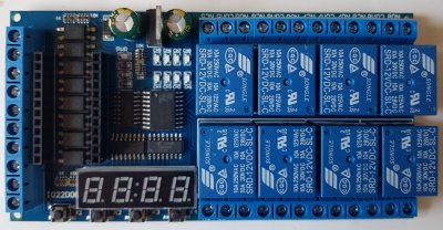
The Board
The additional needed outputs are obtained with the three 74HC595 shift registers.
The relays are not connected in ascending order to shift register U5 but in the order 81234567. The enable input of this shift register for the relays is connected to pin A1. This can be used to activate the outputs after the initialization has been carried out or to implement an emergency shut down.
Two additional shift registers (U3 and U4) are used for the 4-digit 7-segment display. The circuit diagram shows a 18:88 but in fact it is delivered with an 8.8.:8.8. version. The display is common cathode and is soldered directly to the board without a socket. In order to be able to control the mulitplexed LED display data must be sent permanently to the shift registers. I get stable results with a two milliseconds interval. An LED driver like an HT16K33 or MAX7219 would have been a better choice. Pin 13 was selected as the data pin for the shift register, so the LED on the Arduino Pro Mini LED will flicker / glow.
Furthermore, 8 inputs are provided with optocouplers (to be wired against GND) and the inputs are provided with screw terminals.
Additionally there are 4 push buttons on the circuit board.
The pins A4 / A5 are not connected and could be for I2C. The A6 / A7 pins are also available on the Pro Mini (as on the Nano). So in addition to TX / RX, you have a total of 4 other GPIOs at your disposal.
The Arduino Pro Mini is supplied in its socket with VCC = 5V, so a Pro Mini
in the 5V variant must be used. For a Pro Mini 3.3 a slight modification is
needed to route the 5V to RAW.
According to the circuit diagram, the VIN input of the PCB is protected against
polarity reversal with a diode. A simple linear regulator is used to regulate
the voltage to 5 V (according to the circuit diagram, there should be a resistor
R0 with which the voltage regulator can be bridged, but I couldn't make it out
on the circuit board). During operation with the display active, the controller
only gets slightly warm.
The board has no cutouts, therefore do not operate on the 230V power supply!
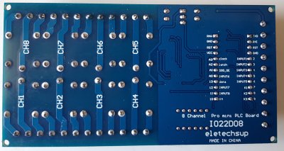
The dimensions of the board are 120 * 62 * 19mm.
The Software for the IO22D08
The vendor provides a link to a quite well commented example sketch. The used timer library will be included in the zip file and ensures that the display is continuously updated.
The sketch implements eight retriggerable relays with delay: if you push one of the optocoupler inputs against GND, the assigned relay switches on for a certain period of time. With buttons 1 - 4 the time parameters or the remaining time of the first four relays can be shown
An Adopted Sketch for the IO22D08
I didn't like usage of a timer and the functions were a little too confused for me. The three shift registers are addressed in a chain. As described above, the display is multiplexing and you have to shift the relays into the registers every time. Therefore I created a base class IO22D08 that implements the hardware of the shift registers (relay and display). The basic class provides the hardware access for the board and can be reused unchanged in all sketches.
The IO22D08timer class is derived from the base class. This class
inherits all methods of the base class and contains additional variables and
methods for time control specific for the sketch. I liked the inheritance better
than two separate classes for this purpose. The object "board" is finally the
instance of IO22D08timer and will be used in the sketch. It will support all
methods:
The optocouplers and push buttons are read in a simple function. All in all, I think the sketch is now more readable and easier to adapt for my purposes.
/* IO22D08 DC 12V 8 Channel Pro mini PLC Board Relay Shield Module for Arduino Multifunction Delay Timer Switch Board Hardware: 4 bit Common Cathode Digital Tube Module (two shift registers) 8 relays (one shift register) 8 optocoupler 4 discrete input keys (to GND) ---Segment Display Screen---- --A-- F---B --G-- E---C --D-- __ __ __ __ |__||__|.|__||__| |__||__|'|__||__| ---------------------- available on Aliexpress: https://s.click.aliexpress.com/e/_A0tJEK some code parts based on the work of cantone-electonics http://www.canton-electronics.com this version by noiasca 2021-04-01 OOP (2340/122) 2021-03-31 initial version (2368/126) 1999-99-99 OEM Version (2820/101) */ //Pin connected to latch of Digital Tube Module // ST Store // de: Der Wechsel von Low auf High kopiert den Inhalt des Shift Registers in das Ausgaberegister bzw. Speicherregister const uint8_t latchPin = A2; //Pin connected to clock of Digital Tube Module // SH clock Shift Clock Pin //de: Übernahme des Data Signals in das eigentliche Schieberegister const uint8_t clockPin = A3; //Pin connected to data of Digital Tube Module const uint8_t dataPin = 13; //Pin connected to 595_OE of Digital Tube Module // Output Enable to activate outputs Q0 – Q7 - first device: Relay IC const uint8_t OE_595 = A1; // A4 - unused - not connected - I2C SDA // A5 - unused - not connected - I2C SCL // A6 - unused - not connected // A7 - unused - not connected const uint8_t optoInPin[] {2, 3, 4, 5, 6, A0, 12, 11}; // the input GPIO's with optocoupler - LOW active const uint8_t keyInPin[] {7, 8, 9, 10}; // the input GPIO's with momentary buttons - LOW active const uint8_t noOfOptoIn = sizeof(optoInPin); // calculate the number of opto inputs const uint8_t noOfKeyIn = sizeof(keyInPin); // calculate the number of discrete input keys const uint8_t noOfRelay = 8; // relays on board driven connected to shift registers byte key_value; // the last pressed key // the base class implements the basic functionality // which should be the same for all sketches with this hardware: // begin() init the hardware // setNumber() send an integer to the internal display buffer // pinWrite() switch on/off a relay // update() refresh the display // tick() keep internals running class IO22D08 { protected: uint8_t dat_buf[4]; // the display buffer - reduced to 4 as we only have 4 digits on this board uint8_t relay_port; // we need to keep track of the 8 relays in this variable uint8_t com_num; // Digital Tube Common - actual digit to be shown uint32_t previousMillis = 0; // time keeping for periodic calls // low level HW access to shift registers // including mapping of pins void update() { static const uint8_t TUBE_NUM[4] = {0xfe, 0xfd, 0xfb, 0xf7}; // Tuble bit number - the mapping to commons // currently only the first 10 characters (=numbers) are used, but I keep the definitions // NO.:0,1,2,3,4,5,6,7,8,9,10,11,12,13,14,15,16,17,18,19,20,21,22 23 24 25 26 27 28*/ // Character :0,1,2,3,4,5,6,7,8,9,A, b, C, c, d, E, F, H, h, L, n, N, o, P, r, t, U, -, ,*/ const uint8_t TUBE_SEG[29] = {0xc0, 0xf9, 0xa4, 0xb0, 0x99, 0x92, 0x82, 0xf8, 0x80, 0x90, 0x88, 0x83, 0xc6, 0xa7, 0xa1, 0x86, 0x8e, 0x89, 0x8b, 0xc7, 0xab, 0xc8, 0xa3, 0x8c, 0xaf, 0x87, 0xc1, 0xbf, 0xff}; uint8_t tube_dat; // Common Cathode Digital Tube, bit negated - sum of all segments to be activated uint8_t bit_num; // digital tube common gemappt auf tuble bit number uint8_t display_l, display_h, relay_dat; // three databytes of payload to be shifted to the shift registers if (com_num < 3) com_num ++; else com_num = 0; // next digit uint8_t dat = dat_buf[com_num]; // Data to be displayed tube_dat = TUBE_SEG[dat]; // Common Cathode Digital Tube, bit negated - sum of all segments bit_num = ~TUBE_NUM[com_num]; // digital tube common gemappt auf tuble bit number display_l = ((tube_dat & 0x10) >> 3); //Q4 <-D1 -3 SEG_E display_l |= ((bit_num & 0x01) << 2); //DIGI0<-D2 +2 display_l |= ((tube_dat & 0x08) >> 0); //Q3 <-D3 0 SEG_D display_l |= ((tube_dat & 0x01) << 4); //Q0 <-D4 -4 SEG_A display_l |= ((tube_dat & 0x80) >> 2); //Q7 <-D5 -2 SEG_DP - Colon - only on digit 1 ? display_l |= ((tube_dat & 0x20) << 1); //Q5 <-D6 1 SEG_F display_l |= ((tube_dat & 0x04) << 5); //Q2 <-D7 5 SEG_C // output U3-D0 is not connected, // on the schematic the outputs of the shiftregisters are internally marked with Q, here we use U3-D to refeer to the latched output) display_h = ((bit_num & 0x02) >> 0); //DIGI1<-D1 0 display_h |= ((bit_num & 0x04) >> 0); //DIGI2<-D2 0 display_h |= ((tube_dat & 0x40) >> 3); //Q6 <-D3 -3 SEG_G display_h |= ((tube_dat & 0x02) << 3); //Q1 <-D4 3 SEG_B display_h |= ((bit_num & 0x08) << 2); //DIGI3<-D5 2 // Outputs U4-D0, U4-D6 and U4-D7 are not connected relay_dat = ((relay_port & 0x7f) << 1); // map Pinout 74HC595 to ULN2803: 81234567 relay_dat = relay_dat | ((relay_port & 0x80) >> 7); //ground latchPin and hold low for as long as you are transmitting digitalWrite(latchPin, LOW); // as the shift registers are daisy chained we need to shift out to all three 74HC595 // hence, one single class for the display AND the relays ... // de: das ist natürlich ein Käse dass wir hier einen gemischten Zugriff auf das Display und die Relais machen müssen shiftOut(dataPin, clockPin, MSBFIRST, display_h); // data for U3 - display shiftOut(dataPin, clockPin, MSBFIRST, display_l); // data for U4 - display shiftOut(dataPin, clockPin, MSBFIRST, relay_dat); // data for U5 - Relay //return the latch pin high to signal chip that it no longer needs to listen for information digitalWrite(latchPin, HIGH); } public: IO22D08() {} void begin() { digitalWrite(OE_595, LOW); // Enable Pin of first 74HC595 pinMode(latchPin, OUTPUT); pinMode(clockPin, OUTPUT); pinMode(dataPin, OUTPUT); pinMode(OE_595, OUTPUT); } // fills the internal buffer for the digital outputs (relays) void pinWrite(uint8_t pin, uint8_t mode) { // pin am ersten shiftregister ein oder ausschalten if (mode == LOW) bitClear(relay_port, pin); else bitSet(relay_port, pin); update(); // optional: call the shiftout process (but will be done some milliseconds later anyway) } // this is a first simple "print number" method // right alligned, unused digits with zeros // should be reworked for a nicer print/write void setNumber(int display_dat) { dat_buf[0] = display_dat / 1000; display_dat = display_dat % 1000; dat_buf[1] = display_dat / 100; display_dat = display_dat % 100; dat_buf[2] = display_dat / 10; dat_buf[3] = display_dat % 10; } // this method should be called in loop as often as possible // it will refresh the multiplex display void tick() { uint32_t currentMillis = millis(); if (currentMillis - previousMillis > 1) // each two milliseconds gives a stable display on pro Mini 8MHz { update(); previousMillis = currentMillis; } } }; // the timer class extends the basic IO22D08 board // with some timers for the relays // this is the specific implementation for this sketch class IO22D08timer : public IO22D08 { protected: bool isActive[noOfRelay]; // timer of this relay is running uint32_t previousTimer[noOfRelay]; // start time of relay public: IO22D08timer() : IO22D08() {} uint16_t delay_time[noOfRelay]; // delay time of this relay - I'm to lazy to write a setter, therefore public void startTimer(byte actual) { // start the timer and activate the output previousTimer[actual] = millis(); isActive[actual] = true; pinWrite(actual, HIGH); } void tickTimer() { // a specialised "tick" method avoiding a virtual/override, hence the different name uint32_t currentMillis = millis(); if (currentMillis - previousMillis > 1) // each two milliseconds gives a stable display on pro Mini 8MHz (3ms will flicker) { // 01 check if there is something to do for the relay timers: for (size_t i = 0; i < noOfRelay; i++) { if (isActive[i]) // check for switch off { if (currentMillis - previousTimer[i] > delay_time[i] * 1000UL) { isActive[i] = false; pinWrite(i, LOW); } } } // 02 update the output buffer if (isActive[key_value]) setNumber(delay_time[key_value] - (millis() - previousTimer[key_value]) / 1000); // calculate remaining time else setNumber(delay_time[key_value]); // just show programmed delay time // 03 default todos as in base class tick: update(); previousMillis = currentMillis; } } }; IO22D08timer board; // create an instance of the relay board with timer extension void readInput() { for (size_t i = 0; i < noOfOptoIn; i++) { if (digitalRead(optoInPin[i]) == LOW) { board.startTimer(i); // activate pin on board } } for (size_t i = 0; i < noOfKeyIn; i++) { if (digitalRead(keyInPin[i]) == LOW) { key_value = i; } } } void setup() { //Serial.begin(9600); // slow for 8mhz pro mini //Serial.println("\nIO22D08 board"); for (auto &i : optoInPin) pinMode(i, INPUT_PULLUP); // init the optocoupler for (auto &i : keyInPin) pinMode(i, INPUT_PULLUP); // init the discrete input keys board.begin(); // prepare the board hardware // set some default values board.delay_time[0] = 16; // 1-9999 seconds, modify the number change the delay time board.delay_time[1] = 2; board.delay_time[2] = 3; board.delay_time[3] = 4; board.delay_time[4] = 5; board.delay_time[5] = 6; board.delay_time[6] = 7; board.delay_time[7] = 8; } void loop() { readInput(); // handle input pins board.tickTimer(); // timekeeping for display/ }
The new sketch should do exactly the same as the Chinese example, but does not require a timer library, uses around 200 bytes less program memory, but 25 bytes more SRAM.
The display output is currently limited to integers. In principle, you could also inherit the IO22D08 from print, but that only makes sense if you also complete the character set, because currently only numbers on some letters are defined (similar to the Chinese example sketch).
Pricing of the IO2D08 Relay Board
This 8 channel relay board is available for aprox. 20 USD. Let's do a comparision with other components:
- 8 channel relay board (8 USD)
- Optocoupler board (12 USD)
- LED display (3,50 USD)
So in total around the same costs, but you don't need messy Dupont wires to connect all components.
Summary on the IO22D08
This
8 channel PLC board fulfills the purpose of a compact assembly.
You have to take care of the optocoupler if you want to connect your own
sensors.
The control of the LED display with shift registers is by far not perfect, but
there are several examples available how to update update the display.
However, since the I2C ports are not used so fare, the purchase is worth the
money for me.
- Video on Youtube
- 8 channel Relayboard available on Aliexpress (*)
- The Chinese Sketch example
- Discussion in arduino.cc Forum
- This page in German
*) Disclosure: Some of the links above are affiliate links, meaning, at no additional cost to you I will earn a (little) comission if you click through and make a purchase. I only recommend products I own myself and I'm convinced they are useful for other makers.
History
First upload: 2021-04-02| Version: 2021-04-03