Fun with millis(): LED, Buzzer, LCD and a Finite State Machine

I came along of a topic in the arduino.cc forum. The thread owner asked for a faster way to switch pins, but during the discussion I observed that the underlying example is worth a rewrite. The example shows how to do several things on an Arduino "in parallel".
Use case: An Anti Car Hijacking Device
The basic idea of the use case is an anti car hijacking device. If activated the car should be stopped after a specific sequence of warnings.
The Functionality of the Sketch - Software Requirements
First summarize the software requirements
- A driver is driving a car equipped with an anti carjacking system that supposed to do the following when any door is opened ignition is on), when ignition is off, that is a whole different situation that I also took into account but do not worry about it for now and let’s just concentrate on, when any door is opened and ignition is on
- The system should start a 30 seconds count down before cutting off ignition and immobilizing the engine, during these 30 seconds countdown, the driver has the option to use a hidden button to disable the countdown
- On second 15, the system buzzer should beep every second
- On second 25, the system buzzer should beep every half second
- On second 30, the ignition should be cut off, engine is immobilized, buzzer has stopped, and car horn should horn every half second
Note: The requirements are slightly simplified in contrast to the original posts. I just wanted to keep the basic functionality.
The Finite State Machine
To keep track of that flow of program steps I introduce a simple finite state machine (FSM) with 5 states:

If the alarm is started the FSM should activate state1 and jump through the states. If the user disarms the alarm, the FSM jumps back to state idle. The FSM is using a switch/case:
void alarmFSM(uint32_t currentMillis = millis()) {
  switch (alarmState) {
    case 0 :
      if (digitalRead(alarmStartPin) == LOW) {
        alarmState++;
        Serial.print(F("silent alarmState=")); Serial.println(alarmState);
        alarmPreviousMillis = currentMillis;
        alarmLed.on(1000);
        alarmIndicator.setOnChar('s');
        alarmIndicator.on(400);
      }
      break;
    case 1: // 0..15
      if (disarmAlarm()) {
        Serial.print(F("alarmOff")); Serial.println(alarmState);
        alarmStop();
        alarmState = 0;
      }
      if (currentMillis - alarmPreviousMillis > 15000UL) {
        alarmState++;
        Serial.print(F("warn alarmState=")); Serial.println(alarmState);
        alarmLed.on(500);
        buzzer.on(1000);
        alarmIndicator.setOnChar('w');
      }
      break;
    case 2: // 15..25
      if (disarmAlarm()) {
        Serial.print(F("alarmOff")); Serial.println(alarmState);
        alarmStop();
        alarmState = 0;
      }
      if (currentMillis - alarmPreviousMillis > 25000UL) {
        alarmState++;
        Serial.print(F("urgent alarmState=")); Serial.println(alarmState);
        alarmLed.on(300);
        buzzer.on(500);
        alarmIndicator.setOnChar('u');
      }
      break;
    case 3: // 25..30
      if (disarmAlarm()) {
        Serial.print(F("alarmOff in ")); Serial.println(alarmState);
        alarmStop();
        alarmState = 0;
      }
      if (currentMillis - alarmPreviousMillis > 30000UL) {
        alarmState++;
        Serial.print(F("cut off alarmState=")); Serial.println(alarmState);
        alarmLed.on(200);
        buzzer.offSmooth();
        horn.on();                       // instead
        alarmIndicator.setOnChar('x');
        digitalWrite(ignitionPin, HIGH); // ignition kill
      }
      break;
    case 4: // after
      if (disarmAlarm()) {
        Serial.print(F("alarmOff in ")); Serial.println(alarmState);
        alarmStop();
        alarmState = 0;
      }
      break;
  }
}
Blink Without Delay using millis()
You could write a simple non blocking "Blink" class for a LED.
class BlinkLed {
  protected:
    const uint8_t pin;
    uint32_t previousMillis = 0;
    uint16_t interval = 1000;
    uint8_t state = 0;

  public:
    BlinkLed(uint8_t pin, uint16_t interval = 1000) : pin(pin), interval(interval) {}

    void begin() {
      pinMode(pin, OUTPUT);
    }

    void on() {
      state = 2;
    }

    void off() {
      state = 0;
      digitalWrite(pin, LOW);
    }

    void update (uint32_t currentMillis = millis()) {
      switch (state) {
        case 1 :
          if (currentMillis - previousMillis > interval)  {
            previousMillis = currentMillis;
            digitalWrite(pin, LOW);
            state = 2;
          }
        case 2 :
          if (currentMillis - previousMillis > interval)  {
            previousMillis = currentMillis;
            digitalWrite(pin, HIGH);
            state = 1;
          }
      }
    }
};
In the end we will need blink classes for "Arduino pins", but also for the buzzer and an indicator on the LCD.
Reusing Code: Class Inheritance
Instead of duplicating code with copy/paste we will introduce a base class without hardware access and let three classes inherit from the base class:

Blink "Anything"
As we want to get different hardware to "Blink" we start to make abstract class without any hardware access. The class Blink will only contain the basic blink logic and some setters to be able to activate and deactivate blinking.
// a generic blink class to toggle a blinking effect on an elemet
class Blink  {
  protected :
    uint32_t previousMillis = 0; // time management for "blinking"
    uint16_t interval = 500;     // default interval
    uint8_t state = 0;           // 0 off, 1 OnPulsephase, 2 offPulsePhase
    bool preStop = false;        // flag to stop after next active phase

  public:
    Buzzer () {}

    virtual void hwWrite(uint8_t level);  // a low level hwWrite must be implemented in the derived class

    void setInterval(uint16_t interval) {
      this->interval = interval;
    }

    void off() {
      hwWrite(LOW);
      state = 0;
    }

    //let the last beep run out
    void offSmooth() {
      if (state == 2)
        off();
      else
        preStop = true;
    }

    void on() {
      hwWrite(HIGH);
      previousMillis = millis();
      state = 1;
      preStop = false;
    }

    void on(uint16_t interval) {
      setInterval(interval);
      on();
    }

    void update(uint32_t currentMillis = millis()) {
      if (state && currentMillis - previousMillis > interval)  {
        previousMillis = currentMillis;
        if (state == 1) {
          hwWrite(LOW);                        // switch off - abstracted from the hardware
          if (preStop) off(); else state = 2;
        }
        else {
          hwWrite(HIGH);                       // switch on - abstracted from the hardware
          state = 1;
        }
      }
    }
};
The keyword virtual means that such a member function will be needed in the derived class. If you don't want to switch off the object hard and let the on effect visible/hearable in the same interval, introduce a "soft off".
Blink a LED, honk a Horn
Obviously, the first hardware we want to control is a discrete Arduino pin. Therefore we write a class and add the hwWrite for a discrete pin. It is just a simple pass through to a digitalWrite.
As a output pin needs to be set to OUTPUT in setup() we add a member function .begin().
class DiscretePin : public Blink {
  protected:
    const uint8_t pin;              // the GPIO to be switched on/off
  public:
    DiscretePin(uint8_t pin) : pin(pin) {}

    void begin() {                  // discrete output pins need a pinMode in setup()
      pinMode(pin, OUTPUT);
    }

    void hwWrite(uint8_t level) override {
      digitalWrite(pin, level);     // just a simple pass through for the digitalWrite
    }
};
The keyword override is an additional check: the virtual function from the base class will be overwritten with the implementation. If we have any typos/wrong signatures we will get a compiler warning.
"Blink" / Beep a Buzzer
If you want to have beep beep beep of a Buzzer
A buzzer needs a pin and a frequency. There are separate commands to switch on/off the buzzer. Therefore the hwWrite differs slightly:
class Buzzer : public Blink {
  protected :
    const uint8_t pin;            // the GPIO for a buzzer
    const uint16_t freq;          // the frequency to beep
  public:
    Buzzer (uint8_t pin, uint16_t freq = 600) : pin(pin), freq(freq) {}

    void hwWrite(uint8_t level) override {
      if (level == LOW)
        noTone(pin);
      else
        tone(pin, freq);
    }
};
Blink an Indicator on the LCD
So what's about a warning indicator on the LCD? Well, we just need the position (column and row) and a character which should appear on the LCD, but the basic logic still comes from our generic Blink class:
// an indicator on the display
// for usual you would also handover the reference to a LCD object, but lets keep it simple
class Indicator : public Blink {
  protected :
    const uint16_t col;          // on which column
    const uint8_t row;           // on which row
    char onChar = '-';           // a sign/char to be shown
    const char offChar = ' ';    // a sign/char if not shown (idle)
  public:
    Indicator (uint8_t col, uint8_t row, char onChar) : col(col), row(row), onChar(onChar) {}

    // output one character to the LCD on the designated place
    void hwWrite(uint8_t level) override {
      lcd.setCursor(col, row); // col, row
      if (level == LOW)
        lcd.write(offChar);
      else
        lcd.write(onChar);
    }

    // modifiy the on character
    void setOnChar(char onChar) {
      this->onChar = onChar;
    }
};
You could even define special characters to be shown - but that is out of scope of this example.
Dealing with the Blinking Hardware Objects
When we have our classes we can create instances of the used Hardware
DiscretePin alarmLed(2);              // pin
DiscretePin horn(8);                  // pin
Buzzer buzzer(7);                     // pin, frequeny
Indicator alarmIndicator(15, 1, 'S'); // col, row, character
Some of our objects need to be called in the setup() - remember - we have to set the pinMode for a discrete Arduino pin:
  alarmLed.begin();
  horn.begin();
And for the time management all objects need to be "updated" in loop():
  // each object needs a tick/timeslice to be able to check if there is something to do
  alarmLed.update(currentMillis);
  buzzer.update(currentMillis);
  horn.update(currentMillis);
  alarmIndicator.update(currentMillis);
By the way: to have just one millis() access I use a local variable currentMillis and call all objects with the same timestamp. If you call the .update() without a parameter, millis() will be called for each object separately.
4 "blinking" objects on different hardware and still no delay().
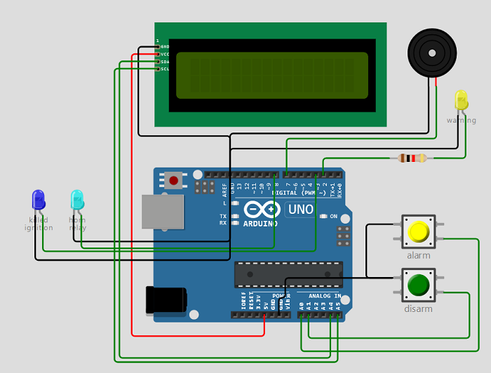
Hardware
So set up the Hardware:
- An emergency button (yellow) to start the alarm sequence
- A (hidden) button (green) to disarm the alarm
- A buzzer
- A relay module to switch on the car horn (in the picture the cyan LED)
- A second relay to kill the car ignition (in the picture the blue LED)
- Let's add a yellow LED to indicate the alarm state
- And then there is a LCD - to demonstrate several "parallel" tasks
The Final Sketch
The full sketch can be copy-pasted from the Wokwi link at the end of the page.
Disclaimer and Warning
This sketch and schematic is a USECASE for programming an Arduino. It is not meant to be used in a real car with real traffic with real people.
Summary
You see you can reuse program logic once written in your sketch and use it multiple times.