The Noiasca Modbus Server Simple Library (Modbus Slave)
The Noiasca Modbus Server Simple is a lightweight library to implement a Modbus Server (former Modbus Slave) on an Arduino or other micrcocontroller.
I split this page in following chapters
- Idea: Why a new Modbus server library
- Holding registers and additional addresses
- Example and proof of concept
- Important member functions
- Caveats & good to know
Idea: Why do we need a new Modbus Server Library?
The Noiasca Modbus Server Library can handle values (2 byte integers) in ascending holding registers. Each additional holding register will expand the array of holding registers. Holding registers will start by default at register 0.
Beside the holding register, you can define additional addresses. These come handy if you want to read actual values only on demand by the Modbus Client without storing them in a holding registers or if you want to switch pins without wasting space for holding register. Further more, additional addresses don't need to be ascending.

Basic Settings of Noiasca Modbus Server Simple
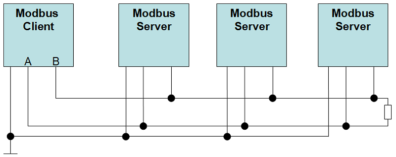
The Modbus is a communication protocol based on top of the RS485.
If you have several Hardware Serial (like on the Arduino MEGA) - you should use one of the Hardware Serials for the Modbus communication. On the Uno you can use SoftSerial at a low baud rate
#include <SoftwareSerial.h>
SoftwareSerial mySerial(2, 3); // RX, TX
I recommend that you declare some constants:
constexpr byte modbus_slave_id = 2;     // Modbus address of this slave
constexpr uint32_t modbus_baud = 19200; // use only slow speeds with SoftSerial
constexpr byte modbus_enable_pin = 11;  // The GPIO used to control the MAX485 TX pin
Now you can use mySerial when you create the Modbus Server Object:
ModbusServer modbusServer(modbus_slave_id, mySerial);
In Setup you will need to call the begin method of your Serial interface:
mySerial.begin(modbus_baud); // start the Serial for Modbus
Usually you will need to control the DE/RE pins on the MAX485. I propose to connect DE/RE and use only one pin. In the example it is called like "modbus_enable_pin". You should define two functions: one to handle the pin before the transmission and one after the transmission:
void cbPreTransmission()
{
  digitalWrite(modbus_enable_pin, HIGH);
}

void cbPostTransmission()
{
  digitalWrite(modbus_enable_pin, LOW);
}
Don't forget to set the pinMode to OUTPUT and set the callback functions in setup()
  pinMode(modbus_enable_pin, OUTPUT);                     // if you need a TX enable pin, set it to output
  modbusServer.setPreTransmission(cbPreTransmission);   // if you need a TX enable pin, set a callback to your pin handling
  modbusServer.setPostTransmission(cbPostTransmission); // if you need a TX enable pin, set a callback to your pin handling
uint16_t update() is the main function of the Modbus Server and should be called in loop() over and over again.
modbusServer.update(); // call Modbus in loop
See the Example 0201_Modubs_Server_HelloWorld for a basic example.
Usage of Holding Registers
This Modbus server holds values in registers of 2 byte length each.
a) define an enumeration with clear text register names. Use the final entry "HOLDING_REGS_SIZE" to determine the size of the array
enum
{
  regButton,         // register 0 - read a button
  regADC0,           // register 1 - analog port 0
  regLED,            // register 2 - set a LED
  regServo,          // register 3 - set a Servo
  HOLDING_REGS_SIZE  // leave this one
};
b) Define an array of a 2 byte variable of size HOLDING_REGS_SIZE
unsigned int holdingRegs[HOLDING_REGS_SIZE]; // function 3 and 16 register array
Use "regButton" instead of a magic number "0" in your sketch. If you need more registers - expand the list.
Each additional register will need 2 bytes of SRAM.
The defined register array makes it very easy to provide values to the client. You just have to update the values in the holdingRegs array:
void updateRegisters()
{
  static uint32_t previousMillis = 0;
  uint32_t currentMillis = millis();
  if (currentMillis - previousMillis > 50)  // this also helps to "debounce" a button
  {
    previousMillis = currentMillis;
    if (digitalRead(buttonPin) == LOW)
      holdingRegs[regButton] = 1;
    else
      holdingRegs[regButton] = 0;
    holdingRegs[regADC0] = analogRead(0);
  }
}
Vice versa you can read the value from the holdingRegs, switch pins or start other activities.
You can set two optional callback function which will be called after the client has read a holding register or after the client has written to a holding register:
  modbusServer.setRegisterWritten(cbRegisterWritten); // FC6/FC16 write: Client has written to a server holding register
  modbusServer.setRegisterRead(cbRegisterRead);       // FC3 read: Client has requested server holding registers
Usage of Additional Addresses
If you need additional addresses which are not ascending and are out of the range of the holding registers you can use following pattern:
a) Define a callback function to make the validation of additional addresses possible. The function must be able to accept a 2 byte address and must return a true (=valid) or false (=invalid address). You can define one specific valid address or ranges of valid addresses:
bool cbIsValidAddress(uint16_t addr)
{
  switch(addr)
  {
    case 100 :             // a valid address
    case 150 :
    case 200 ... 210 :     // a range of valid addresses
    case 1000 ... 1003 :
      return true;
  }
  return false;            // all other addresses will be unvalid
}
b) In setup() inform the library to check the requested registers with this function:
modbusServer.setIsValidAddress(cbIsValidAddress);
c) Define a callback function for incoming write requests. The function must accept a address and the value which should be written to that register.
void cbModbusRegisterSent(const uint16_t address, const uint16_t value)
{
  switch (address)
  {
    case 100: digitalWrite(ledPin, value); break;
    case 150: digitalWrite(motorPin, value); break;
    case 200: aVariable = value; break;
    case 201: anotherVariable = value; break;
    case 200: aThirdVariable = value; break;
  }
}
d) In setup() inform the library to call the function when one of these addresses was used
modbusServer.setRegisterSent(cbRegisterSent); // FC6/FC16 write: Client has sent value to an additional address
e) Vice versa you can define a callback function for read requests. The function must accept an address and must return the value requested from that address.
uint16_t cbRegisterViewed(const uint16_t addr)
{
  Serial.print(F("requested additional address:")); Serial.println(addr);
  switch (addr)
  {
    case 1000: return analogRead(0);
    case 1001: return analogRead(1);
    case 1002: return analogRead(2);
    case 1003: return analogRead(3);
    case 1010: return analogRead(4);
    default: return 0xEEEE;
   }
}
f) and set the function as callback
modbusServer.setRegisterViewed(cbRegisterViewed); // FC3 read: Client has requested an additional address
Coils (FC1, FC5, FC15)
Coils can be compared with controller pins defined as outputs. Modbus provides the FC1, FC5 and FC15 to handle outputs. These function codes fit well for "digitalWrite" and if you want to read back the status with "digitalRead". See the example "Modbus Server FC1 FC5 FC15 Read Write Coils".
To read a pin define a callback. The callback gets the register with an parameter and returns the result of the readed pin
uint16_t cbReadCoil(const uint16_t reg)
{
  //Serial.print(F("FC1 Read Coils, register:")); Serial.println(reg);
  if (digitalRead(coilPin[reg]) == HIGH)   // you could invert the coils if necessary
    return 1;
  else
    return 0;
}
To write to a pin define a callback with two parameters: the register (the address of the pin) and the new value.
A value of 0x0000 should be used to clear the pin (shut pin off). The on value is either 0xFF00 (if the client sent FC5) or 0x0001 (if the client sent FC15)
void cbWriteCoil(const uint16_t reg, uint16_t value)
{
  //Serial.print(F("FC5/FC15 Write Coil, register:")); Serial.println(reg);
  if (value == 0x0000)
    digitalWrite(coilPin[reg], LOW);   // you could invert the coils if necessary
  else
    digitalWrite(coilPin[reg], HIGH);
}
Your server must know how many inputs should be used with Modbus, therefore use following setter:
modbusServer.setNoOfCoils(noOfCoilPin);
Discrete Inputs (FC2)
Discrete inputs can be compared with Arduino pins defined as inputs. Modbus provides the FC2 to read from inputs. See the example "Modbus Server - FC2 Read Discrete Inputs". The callback gets the register with a parameter and returns the result of the readed pin
uint16_t cbReadDiscreteInput(const uint16_t reg)
{
  //Serial.print(F("FC2 Read Discrete Input, Register:")); Serial.println(reg);
  if (digitalRead(inputPin[reg]) == LOW)
    return 1;
  else
    return 0;
}
Your server must know how many "discrete inputs" should be used with Modbus. Therefore use following setter:
modbusServer.setNoOfDiscreteInputs(noOfInputPin);
Holding Registers (FC3, FC6, FC16)
Holding registers can be read (FC3) and written (FC6, FC16). As explained with the hello world example in the previous chapters, you can either use an array to hold all your values or you define additional addresses on top of the holding registers.
Input Registers (FC4)
If you read an input register you will receive a 2 byte value. In terms of Arduino this can be compared with analog pins readed with analogRead. Another example is a temperature sensor or a distance measurement. See the example "Modbus Server FC4 Input Registers".
You will need 2 call back functions: one to validate the address and one to return the requested value.
This example will declare registers 2000 to 2003 and register 3000 as valid FC4 addresses:
bool cbIsValidInputRegister(const uint16_t reg)
{
  switch (reg)
  {
    case 2000 ... 2003 :  // a range of valid input register
    case 3000 :           // a single valid input register
      return true;
    default :
      return false;
  }
}
To return an analog input to the client, you can define a callback which receives the register as parameter. The function must return the result as unsigned integer / 16 bits:
uint16_t cbInputRegisterViewed(const uint16_t reg)
{
  //Serial.print(F("requested input register:")); Serial.println(reg);
  switch (reg)
  {
    case 2000: return analogRead(inputRegisterPin[0]);    // you could read a value on demand
    case 2001: return analogRead(inputRegisterPin[1]);
    case 2002: return analogRead(inputRegisterPin[2]);
    case 2003: return analogRead(inputRegisterPin[3]);
    case 3000: return 3000;                               // you can send back any 2 byte value you need
    default: return 0xEEEE;                               // example for error
  }
}
More Methods in Noiasca Modbus Server Simple
void setStreamEnd(const CallBack cbStreamEnd) will be called when the transmission of several registers has ended.
void setOnClientActivity(void (*cbOnClientActivitiy)()) will be called when a valid client communication (Master) was recognized.
void modbus_update_comms(long baud, unsigned char byteFormat) can be used to modify Modbus parameters during runtime.
Examples and Proof of Concepts
The examples are splitted into "server" and "client". This library focuses on Modbus Server (Modbus Slave). The sketches in the folder "client" are based on the Modbus Master (Library 2.0.0 from Doc Walker) which can be downloaded with the library manager.
Example Basic Hello World
The library comes with a basic "Hello World" example. It shows how to define a Modbus Server object.
Example for the supported Function Codes
For each group of supported Function Codes you find a sketch in the example folder. There is even one example how to set up an Arduino to support FC1, FC2, FC3, FC4, FC5, FC6, FC15 and FC16 in one sketch.
Proof of Concept: Transmit LCD Data Over Long Distances Using Modbus RTU
I2C LCDs are widely used with Arduino. I2C can not be used over long distances, i.e. you should not use an I2C LCD backpack with a PCF8574 over long distances. But you can use Modbus RTU to transmit LCD data from one Arduino to another. Using Modbus you can achieve distances up two 1500m between your main device (client) and your LCD (server). There are several examples how to extend the wires between a "Modbus Client for LCD" and a "Modbus Server for LCD".
On client side you just use a "LCD library" which sends all LCD commands via Modbus. All lcd.begin, lcd.print commands can be reused. Instead of the LCD I2C Extender you must connect the RS485 interface. On the server side you install the LCD Receiver.
Member Functions
In the docs folder of the library you will find a description of all member functions of Modbus Server Simple.
void setPreTransmission (void(*cbPreTransmission)())
Set the callback function for the action before the first byte will be
transmitted.
void setPostTransmission (void(*cbPostTransmission)())
Set the callback function for the action after the last byte was transmitted.
void setIsValidAddress (bool(*cbIsValidAddress)(uint16_t))
Set the callback function to validate received additional addresses. Used in
case of additional addresses for FC3/FC6/FC16.
void setIsValidInputRegister (bool(*cbIsValidInputRegister)(uint16_t))
validate input register. Used for FC4 Read input register
void setRegisterSent (const CallBack cbRegisterSent)
Set the callback function to indicate when client has sent an additional
register FC6/FC16 Write Holding Registers if Holding Register is an additional
address.
void setRegisterWritten (const CallBack cbRegisterWritten)
Set callback function to be called when client has written to a holding
register. FC6/FC16 Write Holding Register.
void setRegisterRead (const CallBack cbRegisterRead)
Set callback function when client has read a holding register. FC3 Read Multiple
Holding register.
void setRegisterViewed (uint16_t(*cbRegisterViewed)(uint16_t))
Client has viewed an additional address FC3 Read Multiple Holding Register.
void setInputRegisterViewed (uint16_t(*cbInputRegisterViewed)(uint16_t))
Client has viewed an input register. FC4 Read Input Register.
int setNoOfCoils (uint16_t newValue)
sets the valid number of coils for FC1/FC5/FC15
void setReadCoil (uint16_t(*cbReadCoil)(uint16_t))
returns one readed Coil from user sketch FC1 Read Coils.
void setWriteCoil (const CallBack cbWriteCoil)
Writes value to coil. FC5 Write Single Coil. FC15 Write Multiple Coils.
void setReadDiscreteInput (uint16_t(*cbReadDiscreteInput)(uint16_t))
returns one discrete input from user sketch. FC2 Read Discrete Input.
void setStreamEnd (const CallBack cbStreamEnd)
transmission of several registers has ended. FC16 Write Multiple Hodling
Registers.
void setOnClientActivity (void(*cbOnClientActivitiy)())
Set callback to indicate when client was active.
int setNoOfDiscreteInputs (uint16_t newValue)
sets the valid number of discrete inputs FC2 Read Discrete Input
void begin (Stream *SerialPort, long baud, uint8_t byteFormat, uint8_t
serverId, uint16_t holdingRegsSize, uint16_t *regs)
configures the Modbus instance
void modbus_update_comms (long baud, unsigned char byteFormat)
modify Modbus parameters during runtime
void setServerId (uint8_t serverId)
modifies the Modbus Server ID (slave ID)
uint16_t update ()
Main "run" function to be called in loop()
Caveats
Currently the NoiascaModbusServerSimple.h supports only the major Modbus RTU function codes FC1, FC2, FC3, FC4, FC5, FC6, FC15 and FC16.
FC3 Read Multiple Holding register: start with 4 and span from 40001 to 49999
FC6 Write Single Holding Register: start with 4 and span from 40001 to 49999
FC16 Write Multiple Holding Register: start with 4 and span from 40001 to 49999
FC2 Read Discrete Inputs: start with 1 and span from 10001 to 19999
FC1 Read Coils: start with 0 and span from 00001 to 09999
FC5 Write Single Coi: start with 0 and span from 00001 to 09999
FC15 Write Multiple Coils: start with 0 and span from 00001 to 09999
FC4 Read input register: start with 3 and span from 30001 to 39999
If you need Modbus TCP on Ethernet/Wifi you should look out for an alternative.
Summary
The Noiasca Modbus Server Simple Library is a Modbus Slave library which uses very similar naming convention and functionality like the Modbus Master Library. It offers to create a Modbus Server with simple implementation for holding registers and also supports the most commonly used function codes.