A Webserver for the ESP8266 or ESP32
This 8 channel relay board is equipped with an ESP8266 12F. It can be programmed with an USB-TTL adapter with the Arduino IDE.
A Webserver for Relay / PWM Boards based on a ESP
I have several different ESP8266 and ESP32 boards and I wanted one generic test sketch. So I came up with the idea to share this sketch with others. The sketch should work for all ESP8266/ESP32 based boards as long as you configure the pins correctly.
A simple Demo Sketch
I have put together a generic demo sketch. It is a simple ESP8266 webserver to switch the relays on or off, read input pins and - if available - sliders for PWM outputs. You can download this sketch at the end of the page.
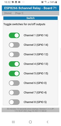
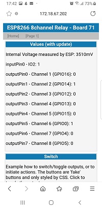
Page 1.htm is just for debugging. It shows the states of all pins and offers simple toggle buttons to switch the relays.
The Generic ESP Webserver Sketch
In general the generic sketch uses arrays of pin definitions. This makes maintenance for different boards very easy.
Before the first compile, got to the main tab and define which board variant you are using.
Example:
#define USE_BOARD 71 // the ESP8266 8 channel board
Don't forget to either set your WiFi credentials or include your settings in the main tab.
This generic webserver sketch is compatible for ESP8266 and the ESP32, hence the precompiler defines to differentiate the boards based on your upload settings.
Hardware Configuration
There are several configuration prepared. They are called "config" followed by a number.
- config1.h
- config65.h
- config71.h
- config76.h
- config79.h
The content of the configuration files is very similar. I'll pick out config76.h as example:
Each file contains an include guard, and ID for the board and a cleartext name which will be printed on the Serial.Monitor and in the header of the webserver.
#pragma once
#if USE_BOARD == 76
#define TXT_BOARDNAME "D1 R32 Board"
As not all boards use Serial for debug outputs, the sketch uses "Terminal" and you assign Serial to the Terminal.
HardwareSerial &Terminal = Serial;
Then you must declare all the pins.
The array inputPins[] hold all GPIOs which should be readed. The name will be used for the prompter on the web interface:
// assign pins to arrays:
Pin inputPin[] {
//pin  name for the website
  {4,  "IO04"},
  {36, "I_36"},
  {34, "I_34"},
  {38, "IO38"},
  {39, "I_39"}
};
Then assign pins to digital outputs (e.g. for relays). The prompter will be printed in the web GUI and you must define if the relay is HIGH active (or low active)
OutputPin outputPin[] {
// pin  name   LOW active or HIGH active
  {2,  "IO02", HIGH},
  {0,  "_0D_", HIGH},
  {14, "IO14", HIGH},
  {27, "IO27", HIGH},
  {16, "IO16", HIGH},
  {17, "IO17", HIGH},
  {25, "IO25", HIGH},
  {26, "IO26", HIGH}
};
If you have hardware to drive PWM pins (e.g. for LED stripes) you define pins and a name for the webgui. You can initialize a start value. The PWM output is a 10 bit value (0..1023).
PWMPin pwmPin[] {
//pin   name   PWM value
  {18, "IO18", 32},
  {19, "IO19", 64},
  {23, "IO23", 128},
  {5,  "IO05", 256},
  {13, "IO13", 512},
  {12, "IO12", 1023}
};
Finally, you can use a LED as indicator for WIFI activity. If you don't have a spare LED available, set the variable to 255:
const byte wifiActivityPin = 2;
#endif
This concludes the basic configuration for a board.
If you only have only one pin for the array just define this one pin. If you don't want to use any pin - don't leave the array empty. Instead delete the array deklaration and replace it with the respective precompiler define
#define NO_PWMPIN
#define NO_INPUTPIN
#define NO_OUTPUTPIN
See the config65.h as example for a board without PWM pins.
Your own Board Configuration
I recommend to give each board in your fleet an individual ID. Create a seperate tab ending with .h
- Copy and paste config1.h to an ID of your choice (e.g. 42) and create new tab
- open tab config.h and add the ID so the compiler can include your board id to the definition
#elif USE_BOARD == 42
#include "config42.h"
- finally change in the maintab the USE_BOARD to your ID
#define USE_BOARD 42 // the actual board to compile:
press compile and upload the sketch to your board.
Summary
This 8 channel relay board is a compact solution if you just need 8 simple relays driven by an ESP8266.