Arduino: Intelligent HAM Antenna Switch

In the following I describe a revised HAM antenna switch that can be connected via several interfaces to HAM radios. This can either be a CAT interface (for example the Icom CI-V protocol) or by reading an analog voltage or an binary encoded band information (e.g. YEASU Linear Jack).
The intelligent HAM antenna switch ensures that an appropriate antenna is connected to the radio depending on the selected frequency. There is no manual switching necessary - all switching is done by the micro-controller in the background, but can be overwritten any time. In the internet you will find an old Arduino sketch from ON7EQ and the available download on this page is an enhancement of that sketch (see credits).
Operation and Program Logic
The operation and the program of the antenna switch works like following:
- An active antenna (relay) can be chosen with the Up / Down buttons.
- If the radio is in transmit mode (PTT pin gets low) – the change from one antenna to another is blocked for security reasons.
- If the antenna is changed, the new selected antenna will be saved into the EEPROM. This will be done for each band separately and happens automatically after a delay of a few seconds.
- The current frequency (QRG) is read from the radio (see the available radio options later). If the current QRG changes, the LCD will be updated. In addition, it is determined whether the new QRG is on a different band.
- If the band changes (due to the change of the QRG), the program will activate the predefined antenna.
- If (for any reason) the frequency is outside of a defined band, the antenna remains unchanged.
- As long as the rig is in receive mode, the antenna can be changed using the Up / Down buttons.
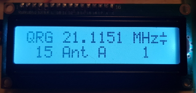
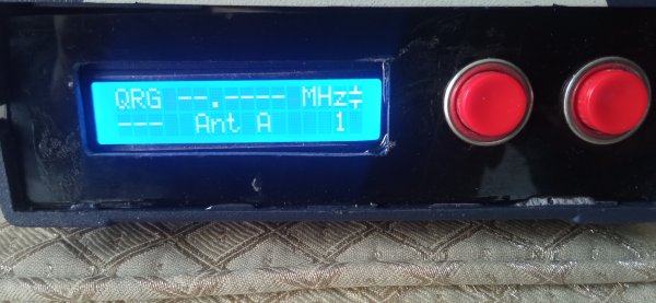
Display Example
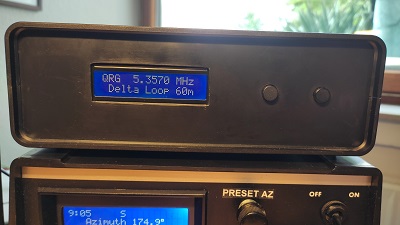
LCD display: The radio is set to a frequency of 21.1151, the intelligent antenna selector automatically switches to the antenna A as it was saved for band 15 previously:
Another antenna can be activated with the Up / down buttons
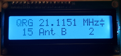
After a short delay, antenna B will be saved to band 15.
Basic Features
- In the case of CAT activity (new QRG information from the HAM radio) this is briefly displayed on the LCD (similar as in the sketch of ON7EQ)
- If values are saved in the EEPROM, this is briefly displayed on the LCD (similar to the code of ON7EQ)
Goodies and Features of this Program
My sketch contains the following changes compared to the ON7EQ sketch:
- The number of outputs is actually only limited by the available pins. An Arduino UNO has 13 "digital" pins and 5 "analog" pins. The sketch uses up to 3 user buttons, a PTT input, two GPIOs for the I2C display, I never use the two 2 HW serial / USB and I also block 2 pins for communication with the radio (even if TX is not used as stated above). 23 - 10 = 13 free pins. My built is for 8 antennas/relays.
- Due to the increased number of outputs, the structure of the second line had to be adopted. Only the current antenna is displayed. As already mentioned, a text description (8 characters) can also be specified in the code.
- If you still want to have the "old antenna display" from ON7EQ with 5 antennas, you only need to adjust the displayShowAntenna() function and recreate the two custom characters. An alternative function is included in the sketch and can be used as a starting point.
- The sketch activates the internal pull-ups for the input buttons. External pull-up resistors are therefore not required (on the other hand - they will not interfere neither).
- The LCD library I used offers several interfaces. I2C is almost "standard", but you can also connect the LCD in parallel with the same library or connect a RGB LCD from Sureeno, use a LCD on a SPI expander and much more. This LCD library can also be found on my homepage. German-speaking readers should definitely take a look at this version if they ever want to write äöüß on the LCD.
- The variable names were changed a lot (starting with a small letter and using camelCase) but are similar to those of ON7EQ, so it should be easy to convert from the old program to this sketch..
- There are no GOTO anymore in the program logic.
- I use OOP, this avoids redundancies and code duplicates. This should also make the conversion to a 20x04 LCD or even to another display very easy as you have every output on one position.
- All your user configuration should be done in a separate configuration file. Use configA.h as an example and modify it to your needs.
- If no QRG is received for a longer time, an "offline indicator" appears on the left in the first row. This shows that either the connection to the radio has been broken or that no frequency change has been made for a long time.
- The readed QRG can be up to 9,9 GHz, so you can use the switch also for 2m, 70cm,... up to 6cm band.
- Each antenna can be given a meaningful name in the sketch. On the pictures I'm using "Ant A" ... "Ant G"´. You can use up to 8 characters.
- Either Soft-Serial (for the UNO) or a HW-Serial (for the MEGA) can be used for the CAT interface to the radio. If you want to change it, you only need to adopt one precompiler #define in your configuration file.
- Since the OM for which I programmed this did not need any different RX - TX antennas, this is currently not supported in the sketch. If you take a closer look at the code, you will see some preparation for it but it is not implemented yet. If this is really a feature that others would like to have, then this could be implemented on request.
- An antenna (relay) will be activated when the device is switched on. If you don't like that, you can change it easily in the sketch. The "default" antenna does not necessarily have to be attached to the first output. As soon as the radio sends the first CAT message, the pre-selected antenna is activated according to the band.
- If you can't use ICOM CI-V, there are several other HW options (e.g. the band pin 5 from the ICOM ACC socket, YAESU Linear Jack,...)
- Support of Arduino UNO/NANO/MEGA and ESP32
- And last but not least: The sketch compiles on a more up-to-date Arduino IDE (mid of 2023 these are Arduino IDE versions 1.8.19 and 2.1.0).
The Arduino Sketch - General Configuration of the Antenna Switch
The sketch is organised in several tabs.
- Main tab: in the main tab you find all common functionality of the program. You MUST activate one configuration file around line 92. There should be no need for other changes in the main tab.
- configXXX.h: this files hold your individual configuration settings. You can modify the pin assignment and activate one interface to your radio. There are several example configurations available. As already mentioned you must activate one configuration file in the main tab.
- input_XXX_YYY: these are internal files needed for the different input interfaces. For usual you don't need to modify anything in these files. Only the activated input interface will be included in your program. Unused interfaces will not occupy any memory.
Supported HAM Radios for the Intelligent Antenna Switch
Currently following HAM Radios / interfaces are supported:
- ICOM CAT CI-V: ICOM CI-V CAT - the first version which was used about one year.
- ICOM ACC socket: pin 5 read the band information from the band pin 5 on the ACC socket. See the separate page for the ACC implementation of the antenna switch for ICOM ACC pin 5 . This second hardware interface was used for another year.
- YAESU Linear Jack: Intelligent Antenna Switch - YEASU Linear Jack - Arduino and HAM is tested with a YAESU FTDX101MP
- YAESU RS232: This version is a prototype how to read the frequence information via RS232 Serial Interface on a YAESU FTDX101MP. It was not used in production. Please use with care.
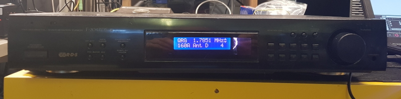
Hardware (V1)
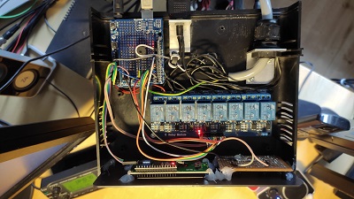
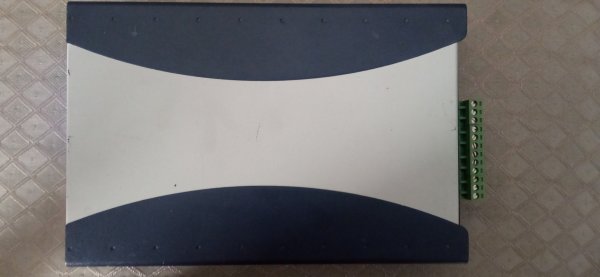
The circuit was built into an old SAT tuner enclosure because I wanted a metal shielding and a transparent front panel to avoid selfmade cutouts for the display:
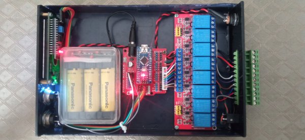
The interior is very simple. I use the original tuner power supply, two step-down converters for 5.0V and 12V (as control voltage for the relay outputs), an I2C LCD, some of the original buttons and an eight channel relay card.
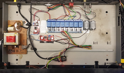
To control the antenna matrix, the activated relays send the 12V control voltage to the antenna switch. The click of the relay also gives a short "accoustic" feedback and you hear, that the antenna has been changed. As microcontroller I use an Arduino NANO Clone (with UNO bootloader). Not a single Dupont cable was used, all connections were soldered and protected with shrink tube.
ESP32 instead of Arduino UNO/NANO/MEGA
In 2022-11 I started to support the ESP32. Why the ESP32? The ESP32 has a lot more capabilities than an UNO/NANO/MEGA. I've chosen the ESP mainly for 3 reasons:
- The ESP32 has an operating voltage of 3.3V. On an ICOM IC-7300 I measured TTL levels of 3.3V. Therefore I wanted to use a 3.3V target for the antenna switch.
- Furthermore if you need a faster communication on serial, the ESP32 has 3 full hardware serials (in contrast to the ESP8266 which has only a TX available on Serial1).
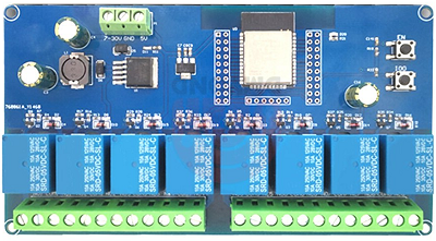
- There is a really nice relay board available which combines an ESP32, a voltage regulator and 8 relays. You just need to add the I2C LCD and some buttons and you are ready to go. If you want to learn more about this board follow this link: ESP32 Relay X8 Board.
The support of the ESP32 made it necessary to add some precompiler defines. Mainly in the context of the EEPROM emulation. Yes I know, EEPROM emulation is deprecated, but as of the implementation (2022-11) it is still supported so I decided to keep the ATmega and ESP32 code as similar as possible. Currently there are no fancy features like WiFi/Webserver, Bluetooth or CAN Bus for the radio shack. It's just the antenna switch like described.
See the configuration file configE32.h for an example.
Ideas for a further Versions and Hardware Alternatives
Even if most parts a premade modules lot of work went into the assembling of the hardware. One of the largest time consumers was the cabling because I didn't want to use these faulty Dupont cables.
Enclosures
I am not satisfied with the look of the enclosure neither, but my manual skills are not sufficient for a do-it-yourself construction. If you invest a little more money, you find what you are looking for in the DIY HIFI section. Different variants are available. The model with the buttons below the display cut out has a really nice finish:
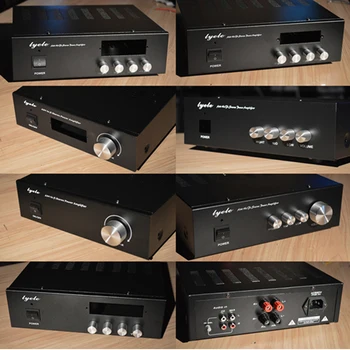
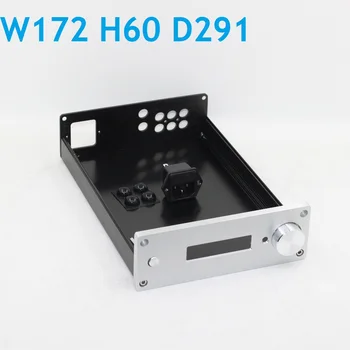
If you are looking for a smaller enclosure, then the version with a rotary control next to the display is ideal. The conversion to an incremental encoder should be quite simple.
Showcase
Here I showcase some antenna switches made by others:
User 1
User 2
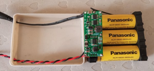
Variant with a backup battery:
Alternatives to the Software (looking back at older versions) - Credits
I would like to give credits to the good work of others:
In 2011 ON7EQ presented an "ARDUINO intelligent antenna matrix switch". The code is also available on his homepage but does not compile any more with the current Arduino IDE.
On his site there is a heavily revised sketch with the reference to "Pete & Sam" ZS6SAM. This sketch also needs adjustments so that it can be compiled with a current IDE. Sam's code was probably created for the Arduino MEGA. During the first few attempts I made the decision to rewrite lot of the parts.
On the DM2RM homepage there is a variant of the original code with the conversion to an I2C display. But even this does not compile with a current IDE. Interesting on his site is a neatly drawn circuit diagram. I just would omit the ULN because you can always invert the relay logic in software.
All mentioned homepages are linked on the end of this page.
Summary
Apart from the programming (the update actually caused more effort than a "finished sketch" would suggest), most of the time actually went into the hardware parts - even if I just used modules. After a periode of over two years the sketch envolved to not only support ICOM radios but also YEASU radios.