Arduino: Intelligent HAM Antenna Switch for ICOM CAT CI-V

In the following I describe a revised HAM antenna switch that can be connected via ICOM CAT CI-V to HAM radios.
The intelligent HAM antenna switch ensures that an appropriate antenna is connected to the radio depending on the selected frequency. There is no manual switching necessary - all switching is done by the micro-controller in the background but can be overwritten any time.
Operation and Program Logic
The operation and the program of the antenna switch works like following:
- An active antenna (relay) can be chosen with the Up / Down buttons.
- If the radio is in transmit mode (PTT pin gets low) – the change from one antenna to another is blocked for security reasons.
- If the antenna is changed, the new selected antenna will be saved into the EEPROM. This will be done for each band separately and happens automatically after a delay of a few seconds.
- The current frequency (QRG) is read from the CAT connection using the Icom CI-V protocol. The Arduino is only reading on the bus. It does NOT send any telegrams in to the bus. If the current QRG changes, the LCD will be updated. In addition, it is determined whether the new QRG is on a different band.
- If the band changes (due to changes of QRG), the program will activate the predefined antenna.
- If (for any reason) the frequency is outside of a defined band, the antenna remains unchanged.
- As long as the rig is in receive mode, the antenna can be changed using the Up / Down buttons.
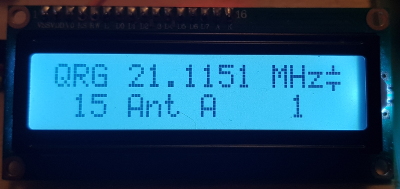
Example: LCD display: The radio is set to a frequency of 21.1151, the intelligent antenna selector automatically switches to the antenna A as it was saved for band 15 previously:
Another antenna can be activated with the Up / down buttons
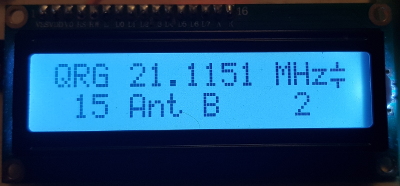
After a short delay, antenna B will be saved to band 15.
Basic Features
- In the case of CAT activity (new QRG messages in CI-V format on the bus) an indicator is briefly displayed on the LCD.
- When values are saved in the EEPROM, this is briefly displayed on the LCD.
Goodies and Features of this Program
My sketch contains the following changes compared to the ON7EQ sketch:
- The number of outputs is actually only limited by the available pins. An Arduino UNO has 13 "digital" pins and 5 "analog" pins. The sketch uses up to 3 user buttons, a PTT input, two GPIOs for the I2C display, I never use the two 2 HW serial / USB and I also block 2 pins for communication with the radio (even if TX is not used as stated above). 23 - 10 = 13 free pins. My built is for 8 antennas/relays.
- Due to the increased number of outputs, the structure of the second line had to be adopted. Only the current antenna is displayed. As already mentioned, a text description (8 characters) can also be specified in the code.
- If you still want to have the "old antenna display" from ON7EQ with 5 antennas, you only need to adjust the displayShowAntenna() function and recreate the two custom characters. An alternative function is included in the sketch and can be used as a starting point.
- The sketch activates the internal pull-ups for the input buttons. External pull-up resistors are not required (on the other hand - they will not interfere neither).
- The LCD library I used offers several interfaces. Most people will use an I2C display, but you can also connect the LCD in parallel with the same library or connect a RGB LCD from Sureeno, use a LCD on a SPI expander and much more. This LCD library can also be found on my homepage. German-speaking readers should definitely take a look at this version if they ever want to write äöüß on the LCD.
- The variable names were changed a lot (starting with a small letter and using camelCase) but are similar to those of ON7EQ, so it should be easy to switch.
- The communication part was taken over from the sketch by "Pete & SAM". This is structured like described in the "Serial Basics 2" in the Arduino.cc forum. Honestly, I wouldn't have done it any other way. The changes are only marginal there.
- There are no GOTO anymore in the program code. I use OOP, this avoids redundancies and code duplicates. This should also make the conversion to a 20x04 LCD very easy as you have every output on one position.
- All your user configuration should be done in a separate config file. Use configA.h as an example and modify it to your needs.
- If you have several devices in your CI-V network, you can set a filter to follow only one specific transmitter. See parameters FILTER_FROM and FILTER_TO in the configuration file.
- Unfortunately CI-V doesn't implement a sanity checks on message level, but there are some basic checks to skip malformed messages.
- And last but not least: The sketch compiles on a more up-to-date Arduino IDE (as of 2023 this us 1.8.19 & 2.1).
- If no QRG is received for a longer time, an "offline indicator" appears on the left in the first row. This shows that either the connection to the radio has been broken or that no frequency change has been made for a long time.
- The readed QRG can be up to 9,9 GHz, so you can use the switch also for 2m, 70cm, ... up to 6cm band.
- Each antenna can be given a meaningful name in the sketch. On the pictures I'm using "Ant A" ... "Ant G"´. You can use up to 8 characters.
- Either SoftSerial (for the UNO/NANO) or a HW-Serial (for the MEGA, ESP32) can be used for the CAT interface to the radio. If you want to change it, you only need to adopt one precompiler #define.
- Since the OM for which I programmed this did not want any different RX - TX antennas, this is currently not supported in the sketch. If you take a closer look at the code, you will see some preparation for it but it is not implemented yet. If this is really a feature that others would like to have, then this could be implemented on request.
- An antenna (relay) will be activated when the device is switched on. If you don't like that, you can change it easily in the configuration file. The "default" antenna can be any of the outputs. As soon as the radio sends the first CAT message, the pre-selected antenna is activated according to the band.
- Support of several Arduino controllers like UNO/NANO/MEGA and ESP32
Program Configuration for the ICOM CAT CI-V
The program can be configured for several different input variants. To use the ICOM CAT CI-V do following:
In the main tab around row 92 you have to activate the configuration file with your program settings. The file configA.h is a working example for the ICOM CI-V interface:
#include "configA.h"
In that tab you can configure the polarity of your relays, the LCD I2C address and assign the pins.
Optionally you can set filters for the incoming messages. You can set the "to" address and/or the "from" address. Check your HAM radio what your device is sending. If there is no other device on the CI-V line you usually don't need any filters. If you have several radios on your CI-V line you can set the FILTER_FROM. Example:
//#define FILTER_TO 0x00 // to Address 00 = broadcast
#define FILTER_FROM 0x94 // from address (e.g. the transmitter sending the QRG)
Two 3.5mm jacks were installed for the CAT interface CI-V. The PTT signal is connected with a cinch socket and passed to a second outlet. This means that the intelligent antenna switch can be easily integrated (daisy chained) into an existing setup.
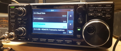
On the transceiver (here an ICOM IC-7300) the CI-V interface must be activated to 9600 baud, but you could chose another baudrate if you adopt the sketch.
ESP32 instead of Arduino UNO/NANO/MEGA
In 2022-11 I started to support the ESP32. Why the ESP32? The ESP32 has a lot more capabilities than an UNO/NANO/MEG. I can recommend the ESP for 3 reasons:
- The ESP32 has an operating voltage of 3.3V. On an ICOM IC-7300 I measured TTL levels of 3.3V. Therefore I wanted to use a 3.3V target for the antenna switch.
- Furthermore if you need a faster communication on serial, the ESP32 has 3 full hardware serials (in contrast to the ESP8266 which has only a TX available on Serial1).
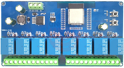
- There is a really nice relay board available which combines an ESP32, a voltage regulator and 8 relays. You just need to add the I2C LCD and some buttons and you are ready to go. If you want to learn more about the read here about the ESP32 Relay X8 Board.
The support of the ESP32 made it necessary to add some precompiler defines - mainly in the context of the EEPROM emulation. Yes I know, EEPROM emulation is deprecated, but currently (2022-11) it is still supported so I decided to keep the ESP32 code as close to the Arduino ATmega code as possible. Currently there are no fancy features like WiFi/Webserver, Bluetooth or CAN Bus for the radio shack. It's just the antenna switch like described.
See the configuration file configE32.h for an example.
Notes about the ICOM CI-V Interface
The CAT interface differs depending on the manufacturer. For ICOM, the CI-V is similar to the serial interface, not with RS232 level but with TTL levels, RX and TX are using one combined line only. The baud rate can usually be set on the radio. I use a slow baudrate of 9600 because of SoftSerial on the Arduino UNO/Nano. The description of the CI-V protocol can be found on the internet. The used ICOM tranceiver only sends the frequency when it changes. If you want to test read the QRG with your PC, you should switch your terminal program to display the data in HEX. A CAT telegrams for CI-V starts with 0xFE 0xFE and ends with 0xFD. My sketch only uses the frequency information.
Summary
Apart from the programming (the update actually caused more effort than a "finished sketch" would suggest), most of the time actually went into the hardware parts - even if I just used modules. Although it was extensively tested with the PC, the setup of the ICOM IC-7300 took a long time. The final connection settings on the IC-7300 could finally be clarified with a direct connection radio -> TTL-USB converter -> laptop and then the intelligent antenna selector worked as planned.