Arduino: Icom HAM Antenna Switch - ACC Version

In the following I describe a revised HAM antenna switch that can be connected via ACC socket to Icom HAM radios. The Icom HAM antenna switch ensures that an appropriate antenna is connected to the radio depending on the selected frequency on the rig. There is no manual switching necessary - all switching is done by the micro-controller in the background, but can be overwritten any time.
Preamble
Most of the implementation work was done for Intelligent Antenna Switch for CI-V. After a stable operation for over one year, the OM decided to expand the setup with an amplifier. Unfortunately the amplifier (a Dressler Tsunami) has connectivity problems if the CI-V line is connected in parallel with the amplifier and the antenna switch. Therefore it was decided to connect the antenna switch to the ACC pin 5 of the ICOM IC-7300.
Operation and Program Logic of the Antenna Switch for the YAESU Linear Jack
For the main program functionalities and options, please see the start page of the Intelligent Arduino Antenna Switch. There are some specifics when reading from the ICOM ACC pin 5:
The operation and the program of the antenna switch works similar to the CI-V version:
- An active antenna (relay) can be chosen with the Up / Down buttons.
- If the radio is in transmit mode (PTT pin gets low) – the change from one antenna to another is blocked for security reasons.
- If the antenna is changed manually, the new selected antenna will be saved into the EEPROM. This will be done for each band separately and happens automatically after a delay of a few seconds.
- The voltage on the ACC socket pin 5 readed and translated in a pseudo frequency (QRG). This QRG is used to lookup the band table.
- If the band changes, the LCD will be updated and the program will activate the predefined antenna.
- If (for any reason) the frequency is outside of a defined band, the antenna remains unchanged.
- As long as the rig is in receive mode, the antenna can be changed using the Up / Down buttons.
Display Example
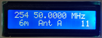
Example: LCD display: The radio is set to a frequency of 50.250, the intelligent antenna selector automatically switches to the antenna A as it was saved for band 6 previously:
When the voltage changes on the ACC pin, another band will be recognized.
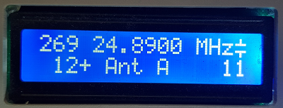
Another antenna can be activated with the [UP] and [DOWN] button.
Program Configuration for the ICOM ACC pin 5
The program can be configured for several different input variants. To use the ICOM ACC pin 5 do following:
In the main tab around row 92 you have to activate the configuration file with your program settings. The file configIAcc.h is a working example for the ICOM ACC pin 5:
#include "configIAcc.h"
In that tab you can configure the polarity of your relays, the LCD I2C address and assign the pins.
To translate the readed ADC value you need to adopt the threasholds (from/to values) for the ADC and assign one frequency:
AdcBandinformation tblAdcBandinformation[] {
// from to   QRG
  {920, 980, 1810},   // 160 --> ADC = 959
  {755, 815, 3500},   // 80 --> ADC = 783
  //                  // 60 no measurement available
  {625, 685, 7000},   // 40 --> ADC = 654
  { 0, 100, 10100},   // 30 --> ADC = 3
  {490, 550, 14000},  // 20 --> ADC = 524
  {380, 440, 18068},  // 17 & 15 --> ADC = 410
  {265, 315, 24890},  // 12 & 10 --> ADC = 285
  {200, 255, 50000}   // 6 --> ADC = 240
};
Hardware for the ICOM ACC pin 5 Variant
The PTT signal is connected with a cinch socket and passed to a second outlet. This means that the intelligent antenna switch can be easily integrated (daisy chained) into an existing setup.
Notes about the band voltage on ACC socket pin 5 of the ICOM IC-7300
I measured two ICOM IC-7300. Both had very similar voltages:
| Band | MHz from |
MHz to |
ACC Voltage |
ICOM open from MHz |
ICOM open to MHz |
|---|---|---|---|---|---|
| 630 | 0,472 | 0,479 | 7,41 | 0,00 | 1,99 |
| 160 | 1,81 | 1,95 | |||
| 80 | 3,50 | 3,80 | 6,07 | 2,00 | 3,99 |
| 60 | 5,25 | 5,45 | 5,07 | 4,00 | 7,99 |
| 40 | 7,00 | 7,20 | |||
| 30 | 10,1 | 10,15 | 0,03 | 8,00 | 10,99 |
| 20 | 14,0 | 14,35 | 4,07 | 11,00 | 14,99 |
| 17 | 18,068 | 18,168 | 3,18 | 15,00 | 21,99 |
| 15 | 21,0 | 21,45 | |||
| 12 | 24,89 | 24,99 | 2,22 | 22,00 | 29,99 |
| 10 | 28,00 | 28,70 | |||
| 6 | 50,00 | 52,00 | 1,88 | 30,00 | 74,80 |
Note: the rig can not differentiate between 630m/160m band, 60m/40m band, 17m/15m band nor 12m/10m band. the last two columns indicate the frequencies on a open ICOM. As an Arduino "analog pin" is only able to measure a voltage up to VCC (roughly 5V) I used a simple voltage divider with two 10K resistors.
Notes of ADC accuracy on the Arduino
The "analog pins" of the Arduino offer a 10 bit ADC. So you can expect values from 0 to 1023. The measurement is relative to the VCC. You can measure the internal voltage on pin AREF. This voltage can (and will) differ based on the method you are providing voltage to your Arduino. So you might get different voltages if you use USB connection, power the Arduino with barrel socket / VIN or via the 5V pin.
Summary
If you can't use CI-V to read the QRG from your ICOM, you might consider to read the band pin on the ACC socket. Not all bands can be differentiated but up to 8 different voltages can be readed and used to switch the antenna.