Arduino: Switch GPIOs by time

Sometimes you want to switch on / off pins on the Arduino based on time. Or you want to start an task with a button press and let it end by time. As you probably now - delay() has it limitations and millis() is your way to go. On this page we want to learn about the usage of millis() and how to design processing flows.
The Use Case
 Assume
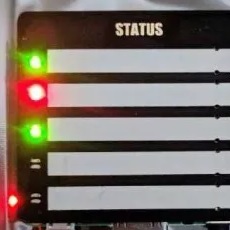
following use case: you have a device which warns you about low water levels
with blinking LEDs. The LEDs are blinking about 1 Hz if the water level is to
low. You are able to read read
the voltage of these LEDs. If a LED starts blinking you want to switch on a
relay which activates a water pump. If the LED stops blinking the relay should
switch off. As the relay should not switch on/off in parallel of the blinking
LED you define to start the relay after a blinking period of 15 seconds (delayOn). If the
LED has stopped blinking for 30 seconds - the relay should switch off (delayOff). The
device has 4 different LEDs and each single LED should activate/deactivate one relay.
Assume
following use case: you have a device which warns you about low water levels
with blinking LEDs. The LEDs are blinking about 1 Hz if the water level is to
low. You are able to read read
the voltage of these LEDs. If a LED starts blinking you want to switch on a
relay which activates a water pump. If the LED stops blinking the relay should
switch off. As the relay should not switch on/off in parallel of the blinking
LED you define to start the relay after a blinking period of 15 seconds (delayOn). If the
LED has stopped blinking for 30 seconds - the relay should switch off (delayOff). The
device has 4 different LEDs and each single LED should activate/deactivate one relay.
The Challenge
Basically you have to solve these challenges
- How can you make this blinking signal to be used as "start signal"?
- How do you identify the end of blinking?
- How can you handle the delays without using delay, as you want to react on more than one LED.
How to Start
Before you open the Arduino IDE, think about the necessary steps which have to be done in the program. There is a phase with the LED permanent off. And a phase when the blink LED is active. Let's call it IDLE and ACTIVE. As this blinking has ON/OFF phases and we need the start of the blinking, we add an phase STARTED. In programming terms we call these phases "states" and we can draw a state diagram:
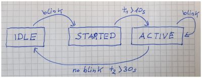
What tells this diagram:
- If the LED starts blinking, switch to status to STARTED.
- If we were 10 seconds in the status STARTED switch to status ACTIVE
- As long as we see a blinking stay in ACTIVE
- If there was no blinking for 30 seconds, go back to IDLE
What is currently not shown but obviously: when you leave STARTED and enter Active you have to switch on the relay. When you leave the ACTIVE state and go back to IDLE - you have to switch off the relay.
Well that is all. You have designed your first "finite state machine" and you can start the IDE now.
Programming a Finite State Machine on the Arduino
This is a complete sketch to copy-paste in the IDE:
/*
  4 input from blinking LED
  4 output controling 4 different relay

  When the LED starts blinking, start timer
  If the LED blinks for certain time, then output  == HIGH
  When the LED stops blinking, wait for a certain time, then output == LOW

  by noiasca
*/

#define DEBUG                                   // deactivate if you don't need debug print
#ifdef DEBUG
#define DEBUG_PRINT(x)    Serial.print (x)
#define DEBUG_PRINTLN(x)  Serial.println (x)
#else
#define DEBUG_PRINT(x)
#define DEBUG_PRINTLN(x)
#endif

enum class State {IDLE,    // LED is OFF
                  STARTED, // after first blink but relais is still kept off
                  ACTIVE   // LED was blinking long enough, Relais is on
                 };

struct Checker {
  const byte readPin;        // GPIO to read the external LED
  const byte relayPin;       // GPIO with a connected relay module
  unsigned long firstBlink;  // "time" of first blink
  unsigned long lastBlink;   // "time" of last blink
  State state;               // actual state
};

Checker checker[] {                            // now we need 4 instances of the LED - relay combination
  {A1, 5, 0, 0, State::IDLE},                  // pin 1 is occupied by Serial!
  {A2, 2, 0, 0, State::IDLE},
  {A3, 3, 0, 0, State::IDLE},
  {A4, 4, 0, 0, State::IDLE}
};

const unsigned long delayFirst = 10 * 1000UL;  // delay after the first recognized blink
const unsigned long delayLast = 30 * 1000UL;   // delay after the last recognized blink

void runCheck()
{
  unsigned long currentMillis = millis();                    // helper variable to store the actual millis ("time");
  for (auto & i : checker)                                   // "for each" element of the struct
  {
    switch (i.state)                                         // do according the current state of the struct
    {
      case State::IDLE :                                     // when you are in IDLE state, then
        if (digitalRead(i.readPin) == HIGH)                  // 1: check for blinking
        {
          DEBUG_PRINT(F("in firstBlink ")); DEBUG_PRINTLN(i.readPin);
          i.firstBlink = currentMillis;
          i.state =  State::STARTED;                         // next state
        }
        break;
      case State::STARTED :                                  // when the blinking has already started, then
        if (currentMillis - i.firstBlink > delayFirst)       // 2: check if blinking is old enough
        {
          digitalWrite(i.relayPin, HIGH);
          i.lastBlink = currentMillis;
          i.state = State::ACTIVE;                           // next state
        }
        break;
      case State::ACTIVE :                                   // when the you are in ACTIVE state, then
        if (digitalRead(i.readPin) == HIGH)
        {
          i.lastBlink = currentMillis;                       // 3: update timer
        }
        if (currentMillis - i.lastBlink > delayLast)         // 4: check if blinking is over long enough
        {
          DEBUG_PRINT(F("in timeout ")); DEBUG_PRINTLN(i.readPin);
          digitalWrite(i.relayPin, LOW);
          i.state = State::IDLE;                             // next state = start from new
        }
    }
  }
}

void setup() {
  Serial.begin(115200);               // we have 2020 - most of serials can scope with 115200 nowadays
  for (auto & i : checker)            // "for each" element of the struct checker
  {
    pinMode (i.readPin, INPUT);
    pinMode (i.relayPin, OUTPUT);
  }
}

void loop() {
  runCheck();
}
Now let's do some analyzes.
We start with some defines for the Serial monitor. During development of the sketch debug print comes very handy to follow the program behaviour. When the sketch is final and ready - we just comment the first #define and all debug prints in the Skech are gone.
#define DEBUG                                   // deactivate if you don't need debug print
#ifdef DEBUG
#define DEBUG_PRINT(x)    Serial.print (x)
#define DEBUG_PRINTLN(x)  Serial.println (x)
#else
#define DEBUG_PRINT(x)
#define DEBUG_PRINTLN(x)
#endif
As you are writing a finite state machine, you want to keep track of the states. Don't use magic numbers. C++/11 comes with a so called enumeration class, which allows you to just name your state:
enum class State {IDLE,    // LED is OFF
                  STARTED, // after first blink but relais is still kept off
                  ACTIVE   // LED was blinking long enough, Relais is on
                 };
The compiler will give each state a number (0, 1, 2) - but you don't care! You will just use the IDLE, STARTED, ACTIVE in your sketch and you can forget about the number behind.
Next step is to define variables. First you need a pin to connect the external LED. Then you obviously you need a pin for the relay. As you want to identify the first blink you need an unsigned long to store the time (millis). The same applies for the end of blinking. And finally - you have to keep track of the status. Keep your variables tidy! Put together what belongs together. To "bundle" variables - to give them a structure, you use the C++ keyword struct:
struct Checker {
  const byte readPin;        // GPIO to read the external LED
  const byte relayPin;       // GPIO with a connected relay module
  unsigned long firstBlink;  // "time" of first blink
  unsigned long lastBlink;   // "time" of last blink
  State state;               // actual state
};
This defines a struct Checker with 5 member variables.
As described in the use case, you need these variables 4 times. Better: you have to define 4 instances of this structure. To make the handling easier, but them in an array:
Checker checker[] {                            // now we need 4 instances of the LED - relay combination
  {A1, 5, 0, 0, State::IDLE},                  // pin 1 is occupied by Serial!
  {A2, 2, 0, 0, State::IDLE},
  {A3, 3, 0, 0, State::IDLE},
  {A4, 4, 0, 0, State::IDLE}
};
The next part is easy: here are some variables you can use as parameter for the state machine:
const unsigned long delayFirst = 10 * 1000UL;  // delay after the first recognized blink
const unsigned long delayLast = 30 * 1000UL;   // delay after the last recognized blink
Now the heavy part: The finite state machine. First you "remember" the current time in a variable
void runCheck()
{
  unsigned long currentMillis = millis();                    // helper variable to store the actual millis ("time");
You want to handle 4 LEDs - but you don't want to write code 4 times. As you have the variables in an struct array, you can use a for loop. Better - you can use something new:
for (auto & i : checker) // "for each" element of the struct
C++/11 comes with the so called ranged based for loop. You have defined a structure, auto inherits the type of the checker. The actual element will get a reference on &i. In other words: you can use i like the actual instance with all member variables. Instead to write checker[0].readPin for the first pin, you just write i.readPin - nice, isn't it?
Now we can handle the state machine. To use a switch-case is straight forward. To define each case, you simple use
what happens in State::IDLE
 {
    switch (i.state)                                         // do according the current state of the struct
    {
      case State::IDLE :                                     // when you are in IDLE state, then
        if (digitalRead(i.readPin) == HIGH)                  // 1: check for blinking
        {
          DEBUG_PRINT(F("in firstBlink ")); DEBUG_PRINTLN(i.readPin);
          i.firstBlink = currentMillis;
          i.state =  State::STARTED;                         // next state
        }
        break;
If the Arduino detects a HIGH, the current timestamp will be copied to the member variable firstBlink AND the next state is "STARTED".
      case State::STARTED :                                  // when the blinking has already started, then
        if (currentMillis - i.firstBlink > delayFirst)       // 2: check if blinking is old enough
        {
          digitalWrite(i.relayPin, HIGH);
          i.lastBlink = currentMillis;
          i.state = State::ACTIVE;                           // next state
        }
        break;
In STARTED you check if enough time is passed and after the defined time you switch on the relay and hand over to the next State::ACTIVE.
In ACTIVE you have to do two steps: every time you see a blink you update the timestamp for lastBlink:
     case State::ACTIVE :                                   // when the you are in ACTIVE state, then
        if (digitalRead(i.readPin) == HIGH)
        {
          i.lastBlink = currentMillis;                       // 3: update timer
        }
Additionally you check, if the time of the lastBlink has expired - and if so: you switch off the relay and go back to State::IDLE
       if (currentMillis - i.lastBlink > delayLast)         // 4: check if blinking is over long enough
        {
          DEBUG_PRINT(F("in timeout ")); DEBUG_PRINTLN(i.readPin);
          digitalWrite(i.relayPin, LOW);
          i.state = State::IDLE;                             // next state = start from new
        }
    }
  }
}
The setup is only a 3 liner with a Serial.begin and the setting of the pinmodes. Again you use the "range based for" and set all 8 pinmodes in just 2 lines:
void setup() {
  Serial.begin(115200);               // we have 2020 - most of serials can scope with 115200 nowadays
  for (auto & i : checker)            // "for each" element of the struct checker
  {
    pinMode (i.readPin, INPUT);
    pinMode (i.relayPin, OUTPUT);
  }
}
Finally you just call the finite state machine in your loop as often as possible.
void loop() {
  runCheck();
}
As long as you write non-blocking code - you can add new functionalities to the loop. What's about a heartbeat LED for your Arduino to see everything is fine with your Arduino?